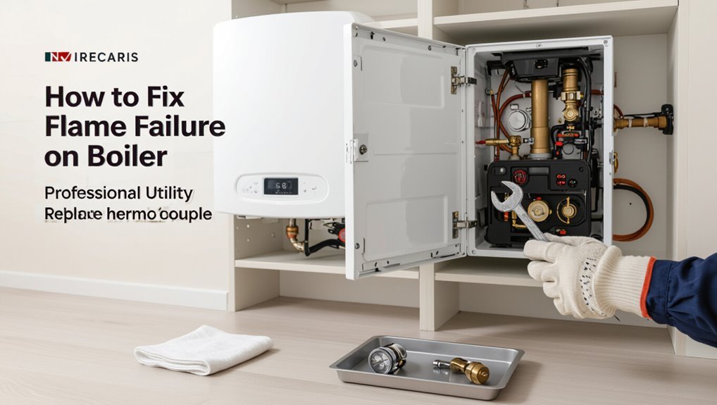
How to Fix Flame Failure on Boiler: Quick Troubleshooting & DIY Repairs
If you’re experiencing flame failure on your boiler, it’s often due to dirty sensors, blocked burners, faulty igniters, trapped air in gas lines, or loose wiring. To troubleshoot, first shut off the power and gas. Then, inspect the pilot light and burners, clean the flame sensor or thermocouple, and tighten any loose electrical connections. Follow the manufacturer’s procedure for a controlled relight. Replace any damaged components and ensure a steady, blue flame. If issues persist, further step-by-step guidance and safety checks are available below.
What Causes Flame Failure in Boilers and Why It Needs Immediate Attention
Flame failure in boilers compromises both safety and heating performance by risking gas leaks, loss of heat, and potential carbon monoxide buildup.
It commonly presents as sudden loss of heat, repeated pilot light outages, unusual burner noises, or error codes on the control panel.
Recognizing these symptoms promptly is essential to prevent hazards and restore reliable operation.
How flame failure affects safety and heating performance
A sudden loss of the pilot or main burner undermines both safety and heating performance by interrupting combustion and triggering automatic shutdowns.
Flame failure raises carbon monoxide and unburned fuel risks, disables heating cycles, and can damage components.
Prompt diagnosis—following guidance on how to fix flame failure on boiler—restores safe combustion, prevents system strain, and maintains reliable heat delivery throughout the property.
Common symptoms that indicate flame failure
Loss of the pilot or main burner is often signaled by several clear, observable symptoms that warrant immediate attention.
Indicators include repeated boiler shutdowns, weak or absent flame, clicking or sparking without ignition, gas smell near the unit, fluctuating pressure or temperature, abnormal soot or yellow flame, and persistent pilot light outages.
These signs demand prompt inspection to prevent hazards and restore function.
Quick Diagnostic Checklist to Confirm a Flame Failure
The reader is advised to begin with simple visual and audible checks—inspect pilot and burner flames for color and stability, and listen for unusual sounds—before any physical contact with the unit.
Essential tools such as a multimeter, combustion analyzer or gas detector, flashlight, and insulated hand tools should be assembled for basic troubleshooting.
If flames remain absent, fluctuate erratically, or gas odors are detected, the boiler should be shut down immediately and a qualified technician contacted.
Visual and audible checks to perform before touching the boiler
Begin by observing and listening around the boiler to gather immediate clues before any hands-on work begins.
Check for visible flame through the sight glass, pilot light condition, soot, corrosion, or gas smell.
Listen for unusual clicking, hissing, or combustion sounds.
Note ignition attempts, repeated shutdowns, and any error codes displayed.
Record observations for safe troubleshooting.
Tools to have on hand for basic troubleshooting
A compact toolkit and a short checklist streamline initial flame-failure diagnostics: a multimeter for voltage and continuity checks, a manometer or pressure gauge for gas-pressure verification, a handheld combustion analyzer or portable CO detector for unsafe combustion, a flashlight and mirror for sight-glass inspection, insulated screwdrivers and nut drivers for safe component access, a soft-bristle brush and canned air for cleaning sensors and pilot orifices, and manufacturer-specific error-code documentation or a service manual for reference.
Also include replacement fuses, spare thermocouple or flame sensor probes, zip ties, dielectric grease, and labels for wiring.
Record readings, photograph connections, and note error codes before reassembly to support accurate troubleshooting and any follow-up service.
When to shut down the boiler and call a professional
Several clear signs indicate immediate shutdown and a call to a qualified technician when flame failure is suspected: persistent ignition attempts, gas odor, repeated lockouts, visible damage to burner or controls, unexplained pressure drops, or carbon monoxide alarm activation.
If basic checks (gas supply, pilot, vents) fail to resolve the issue, power down the boiler, isolate fuel, ventilate, and contact a licensed service professional immediately.
Step-by-Step Troubleshooting for Flame Failure
The technician follows a clear, sequential approach to isolate and resolve common causes of flame failure.
Key checks include:
- Fuel supply and pressure for gas, oil, or LPG
- Pilot/ignition system and flame sensing (thermocouple)
- Gas valve/solenoid operation and burner/electrode condition
- Cleaning or replacing clogged burners and electrodes
Actions proceed from simple to complex, documenting findings and testing the system after each corrective step.
Check the fuel supply (gas, oil, LPG)
Begin by confirming that fuel reaches the boiler: inspect visible gas, oil, or LPG supply lines, valves, and fuel meter/readings for obvious interruptions, leaks, or closed isolation valves.
Verify service tap positions, pressure readings and tank levels.
Look for signs of contamination, frozen pipes, or blocked filters/strainers.
If anomalies appear, isolate supply and contact a qualified technician for safe corrective action.
Inspect the pilot light and ignition system
After verifying fuel delivery, attention should turn to the pilot light and ignition system, since a fault there is a common cause of flame failure.
Inspect pilot flame size, color, and stability; clean or replace clogged pilot orifice.
Check electronic igniter for cracks, corrosion, and proper spark.
Verify wiring connections, switches, and control modules.
Note any intermittent operation and document findings for repair.
Test the flame sensor or thermocouple
Next, test the flame sensor or thermocouple to confirm whether the boiler’s flame-detection device is reliably signaling burner operation.
Visually clean the sensor rod with fine emery cloth, then reconnect.
Measure output: thermocouple should produce ~25–30 mV when heated; flame sensor should register microamps on a multimeter.
Replace if readings are absent or intermittent; retest ignition cycle for consistent flame confirmation.
Examine the gas valve and solenoid operation
With the flame sensor or thermocouple verified, attention shifts to the gas valve assembly and its solenoid, since these components control fuel flow and directly affect flame presence.
Inspect for loose wiring, corrosion, or physical damage. Measure solenoid coil resistance versus specification, confirm valve actuates when energized, and check pilot pressure.
Replace the valve or solenoid if readings or movement are out of tolerance.
Clean or replace clogged burners and electrodes
Begin by shutting off fuel and power to the boiler and allowing components to cool.
Then visually inspect burners and electrodes for soot, deposits, or damage that could disrupt ignition or combustion.
Remove burners per manufacturer instructions, clean ports with a soft brush and compressed air, gently clean or replace electrodes, reseat components, and test ignition.
Replace severely corroded parts.
Verify correct air supply and flue draft
Check that the boiler has an adequate air supply and proper flue draft, since insufficient combustion air or a blocked/poorly drafting flue commonly causes flame failure.
Inspect intake vents for obstructions, confirm room ventilation, and examine the flue for soot, nests, or damage.
Measure draft with a manometer if available.
Correct blockages and verify seals or dampers aren’t restricting exhaust.
Reset procedures and safe restart steps
When a boiler experiences flame failure, follow a clear, safe reset and restart sequence to isolate the fault, restore combustion, and confirm normal operation without introducing hazards.
Isolate fuel and power, wait prescribed purge time, then reset control per manufacturer instructions.
Restore fuel, energize ignition, observe flame detector and combustion stability.
If alarms persist or uncertainty remains, stop and contact a qualified technician.
DIY Repair Procedures You Can Safely Perform
The section outlines practical DIY tasks homeowners can safely attempt to address flame failure.
It covers cleaning the flame sensor or thermocouple with basic tools, safely adjusting or relighting the pilot, and a brief overview of replacing common parts such as thermocouples, igniters, and filters.
It also highlights tightening electrical connections and inspecting wiring while noting when to stop and call a professional.
Cleaning the flame sensor or thermocouple: tools and steps
Begin by gathering a small set of basic tools—fine-grit emery cloth or a non-abrasive scouring pad, a clean rag, a screwdriver, and, if available, a multimeter—so the cleaning can be done efficiently and safely.
Power off and disconnect gas/electric.
Remove sensor mounting screw, gently clean tip, wipe residue, inspect for damage.
Reinstall, restore power, test for continuity with multimeter.
Adjusting or relighting the pilot light safely
Relight the pilot only after confirming power and gas are shut off, adequate ventilation exists, and the homeowner is comfortable following manufacturer instructions and local codes.
Inspect pilot assembly for debris, clear with compressed air, then follow the boiler’s relight procedure: turn control to “pilot,” depress gas knob while applying a long lighter or built‑in igniter, hold for prescribed duration, then release and verify stable flame before restoring normal operation.
Replacing common fault parts (thermocouple, igniter, filters) step overview
After verifying the pilot is stable or safely shut off, homeowners can move on to replacing common fault parts that often cause flame failure: thermocouples, igniters, and inline filters.
Remove power and gas, note orientation, detach the faulty component, install the correct replacement, secure fittings, and restore services.
Test operation and inspect for leaks or irregular flame behavior before finalizing the repair.
Tightening electrical connections and checking wiring
Inspecting and tightening electrical connections is a straightforward, high-impact step homeowners can safely perform to address intermittent flame failure.
The boiler should be powered off and isolated. Visually inspect wires, terminals, and connectors for corrosion, charring, or looseness.
Tighten screws and re-seat plugs with insulated tools. Replace damaged wiring or consult a qualified electrician if uncertainty or persistent faults remain.
When Problems Indicate a Professional Service Is Required
Certain patterns—repeated ignition failures, unexplained noises, or error codes—signal complex faults best handled by certified technicians.
Any suspected gas leaks or issues affecting fuel supply carry safety and legal implications that require professional intervention and adherence to regulations.
Callers should be prepared to describe symptoms clearly and send photos of the boiler label, control panel, and any visible damage to expedite an accurate assessment.
Complex symptoms that need certified technicians
Recognize that some flame-failure signs go beyond routine troubleshooting and require a certified technician.
Persistent intermittent ignition, unexplained pressure or temperature spikes, recurring safety cutouts, abnormal combustion smells or soot, and electrical control board faults demand professional diagnosis.
Certified technicians can perform advanced combustion analysis, gas flow testing, sealed-system inspection, and replace components safely, reducing risk and preventing further damage.
Gas-related risks and legal/regulatory considerations
Why might a flame failure suggest more than a mechanical fault? A persistent failure can indicate gas leaks, improper combustion, or ventilation breaches posing explosion, CO poisoning, and fire risks.
Legal and regulatory frameworks often mandate certified gas-safe inspection and repair; unlicensed intervention may violate codes and void warranties.
Immediate cessation of DIY attempts and contacting qualified professionals is advised to guarantee safety and compliance.
What information and photos to provide to a service call
What should be ready before the technician arrives:
- A concise account of symptoms.
- The boiler’s make, model, and age.
- Recent service history.
- Any error codes or indicator lights displayed.
- The sequence of events leading to the failure.
Include clear photos of the control panel, burner area, labels, pipework, and combustion chamber.
Note unusual smells, sounds, and dates/times of occurrences.
Preventive Maintenance to Reduce Future Flame Failure
A clear inspection schedule—monthly visual checks and seasonal professional inspections before winter and summer—helps catch issues early and reduce flame failure risk.
Homeowners can perform simple tasks such as cleaning vents, checking pilot lights, and ensuring adequate airflow around the boiler.
Proactive replacement of worn parts like thermocouples, filters, and pressure relief valves, plus watching for corrosion, soot buildup, or unusual noises, prevents many failures.
Recommended inspection schedule and seasonal checks
Monthly visual checks, quarterly functional tests, and annual professional inspections together form a practical cadence to catch wear, contamination, or sensor drift before they cause flame failure.
Inspect combustion chamber, pilot assembly, vents, and condensate drains seasonally—before winter and after heavy summer use.
Log findings, note trend changes in flame quality or ignition times, and schedule corrective servicing when deviations exceed manufacturer tolerances.
Simple homeowner maintenance tasks
Perform basic maintenance tasks regularly to reduce the risk of flame failure and extend boiler life.
Homeowners should keep the boiler area clean, guarantee vents and flues are unobstructed, check for leaks, and bleed radiators to prevent airlocks.
Test controls and pilot light operation periodically, tighten accessible electrical connections, and record observations.
Schedule professional service for complex issues or safety checks.
Parts to replace proactively and signs of wear
Following routine homeowner checks and timely professional inspections, attention should turn to specific components that commonly wear out and can precipitate flame failure if neglected.
Replace worn igniters, thermocouples, flame sensors, gas valves, and air filters on recommended intervals.
Inspect burners for corrosion, pilot tubing for leaks, and wiring connectors for looseness or scorching.
Document replacements and schedule future checks.
Troubleshooting Scenarios and Solutions
The section presents common troubleshooting scenarios and concise remedies to guide technicians and homeowners through likely causes of flame failure.
- Intermittent flame failure with cold starts
- Flame failure after boiler cleaning or servicing
- Failure following power outage or gas supply interruption
- Flame failure with error codes (interpreting common codes)
Each scenario is paired with targeted checks and corrective steps to restore reliable ignition.
Intermittent flame failure with cold starts
When a boiler lights reliably after warm cycles but fails to sustain flame during cold starts, the issue most often stems from components or conditions that are sensitive to temperature—such as sluggish gas valves, weak ignition transformers, condensate-blocked pressure switches, or thermal-related wiring connections.
Therefore, troubleshooting should prioritize cold-environment checks, timed observation of the ignition sequence, and comparison of behavior between cold and warm starts to isolate the root cause.
Technicians should test valve response times, measure transformer output under cold load, inspect pressure switch drain paths for ice or blockage, and probe connectors for intermittent contact, replacing parts or adding insulation/heating as indicated.
Flame failure after boiler cleaning or servicing
Several common causes can produce flame failure immediately after cleaning or servicing a boiler, often stemming from disturbed wiring, misadjusted components, or residual debris.
Technicians should verify sensor connections, guarantee burners and pilot jets are unobstructed, and confirm correct electrode gaps and alignment.
Check gas valve seating and ignition sequence settings.
Reassemble panels securely and perform a controlled restart with observation for safe operation.
Failure following power outage or gas supply interruption
Power interruptions or interrupted gas supply often leave a boiler unable to relight due to locked safety interlocks, depleted ignition retries, or residual air in gas lines.
Technicians should reset power, wait recommended purge times, and cycle the boiler per manufacturer instructions.
Verify gas meter & supply, bleed trapped air if safe, and inspect safety valves and pressure.
If unresolved, call a qualified engineer.
Flame failure with error codes interpreting common codes
After addressing outages and supply interruptions, attention turns to interpreting boiler error codes that accompany flame-failure events.
Technicians consult the manual for specific numeric or alphanumeric codes—common ones indicate ignition failure, thermocouple fault, gas valve stuck, or flame sensor issues.
Codes guide targeted checks: electrode gap, sensor cleanliness, gas pressure, wiring integrity.
Reset procedures and service calls follow code severity.
Comparison of Common Components That Cause Flame Failure
A concise comparison highlights how thermocouples and flame sensors differ in symptoms, expected lifespan, and ease of replacement, while igniter systems (spark and hot surface) present distinct failure modes and fixes. The following table summarizes key contrasts to guide diagnosis and repair decisions. Brief, component-focused guidance aids technicians in prioritizing checks and parts.
| Component Pair | Key Differences |
|---|---|
| Thermocouple vs. Flame Sensor | Symptoms, lifespan, replacement complexity |
| Spark Igniter vs. Hot Surface Igniter | Failure modes and typical fixes |
| Practical Impact | Diagnostic priority and parts/skill required |
Thermocouple vs. Flame Sensor: symptoms, lifespan, replacement complexity
Distinguishing between a thermocouple and a flame sensor helps pinpoint the cause of boiler flame failure and directs the correct repair approach.
A thermocouple (pilot systems) shows intermittent shutdowns, lasts 3–7 years, and is low-cost, simple to replace.
A flame sensor (direct ignition) fails causing brief lockouts, lasts 2–5 years, is delicate, often needs cleaning or precise replacement and alignment.
Igniter types: spark vs. hot surface failure modes and fixes
When ignition fails, the problem usually traces to either a spark igniter or a hot surface igniter, each exhibiting distinct failure modes and remedies.
Spark igniters suffer electrode erosion, misalignment, or ignition transformer faults; inspect gaps, clean, and test for HV output.
Hot surface igniters crack, glaze, or burn out; replace if resistance is open or surface damaged.
Follow safety lockout and manufacturer specs.
Safety Checklist After Repair or Troubleshooting
After repairs or troubleshooting, the technician confirms combustion stability and proper venting to guarantee safe operation.
Carbon monoxide risks are addressed by testing for leaks and recommending functioning detectors.
All work is documented, including replaced parts and the next scheduled service date.
Verifying combustion stability and venting
Confirm combustion stability and venting performance before returning the boiler to regular service.
Technicians should observe steady flame shape and color, consistent burner cycles, and stable gas pressure.
Inspect flue and venting for obstructions, leaks, proper pitch, and secure joints.
Verify draft and exhaust temperatures within specifications.
Document readings and correct any deviations; only then resume normal operation.
Carbon monoxide precautions and detector recommendations
1 clear safety step is to guarantee carbon monoxide (CO) risks are addressed before returning the boiler to service: verify functioning CO detectors, confirm alarm placement and battery/back-up power, and brief occupants on evacuation and notification procedures if CO is detected.
Additionally, test detectors after repair, install units near sleeping areas and equipment, replace expired sensors, and recommend professional inspection if any alarm activates.
Documentation: recording repairs, parts, and next service date
With carbon monoxide risks addressed and detectors verified, attention shifts to documenting the repair actions and safety checks performed.
The technician records date, time, fault diagnosis, steps taken, replaced parts with part numbers, and serial numbers.
Test results, gas pressures, flame characteristics, and safety interlock status are logged.
A recommended next service date and contact details are noted for follow-up and warranty tracking.
Quick Reference: Common Causes and One-Line Fixes
A concise checklist highlights the most common causes of flame failure and gives one-line remedies for quick troubleshooting.
- Fuel supply issues — check valves, pressure, and tank level.
- Dirty sensors or burners — clean or replace sensing elements and burner surfaces.
- Faulty ignition components — test and swap ignition leads, electrodes, or igniters.
- Venting and airflow problems — clear obstructions and verify flue draft.
Use this list as an immediate reference before performing in-depth diagnostics.
Fuel supply issues
Check for interruptions or irregularities in the fuel feed that commonly cause flame failure; this category covers issues with gas pressure, supply line blockages, empty or contaminated oil tanks, and faulty valves or regulators.
Inspect supply pressure, confirm gas meter and shutoff valve positions, clear visible blockages, verify oil level and quality, and test regulator and solenoid function.
Replace or service faulty components as needed.
Dirty sensors or burners
Several common flame failures stem from dirty sensors or burners that impair flame detection or combustion quality.
Contaminants, soot, or carbon deposits on flame sensors, electrodes, or burner ports prevent proper ionization and stable combustion.
Clean sensors with fine abrasive or alcohol, clear burner jets with appropriate tools, and inspect for corrosion.
Reassemble and test; recurring fouling indicates combustion tuning or service.
Faulty ignition components
Diagnose faulty ignition components by identifying common failures and pairing each with a concise corrective action.
Igniter failure: replace faulty spark or hot surface igniter.
Ignition module fault: swap module or reset per manufacturer.
Electrode misalignment: realign and secure electrode gap.
Wiring/connectors corroded: clean or replace connectors.
Faulty flame sensor: clean or replace sensor to restore reliable detection.
Venting and airflow problems
After addressing ignition component faults, attention turns to venting and airflow problems, which often prevent proper combustion or cause intermittent flame loss.
Common causes include blocked flues, clogged air intakes, faulty draft regulators, and improper ventilation.
One-line fixes: clear obstructions, clean intake filters, inspect/replace draft devices, guarantee adequate room ventilation, and verify correct flue pitch and seals to restore steady combustion.
Conclusion
In summary, the guide shows practical steps to diagnose and often resolve boiler flame failure safely, yet some readers may worry complex tasks need visuals. A simple mental flowchart—inspect fuel/electrical supply, check ignition/thermocouple, test airflow/venting, then gas valve/sensors—helps visualize progression from basic to advanced causes. If any step feels unclear or unsafe, stop and call a qualified engineer: professional assessment prevents damage and guarantees compliant, reliable repairs.