How to Tell If a Pressure Switch Is Bad: 9 Easy Diagnostic Tests and Fixes
If you’re wondering how to tell if a pressure switch is bad, look for signs like erratic cycling of your pump or HVAC system, failure to start or stop at the set pressures, visible corrosion, unusual smells, or intermittent clicking sounds. To diagnose the issue, conduct a visual inspection, perform multimeter continuity and voltage tests, manually activate the pressure, and verify the cut-in and cut-out pressures using a gauge. Additionally, check for blockages or damage in the tubing and diaphragm, tighten any loose terminals, and clean the contacts. If you notice pitting or a failed diaphragm, replacement will be necessary. Further steps and detailed test instructions are provided below.
How to Tell If a Pressure Switch Is Bad Quick Diagnostic Summary
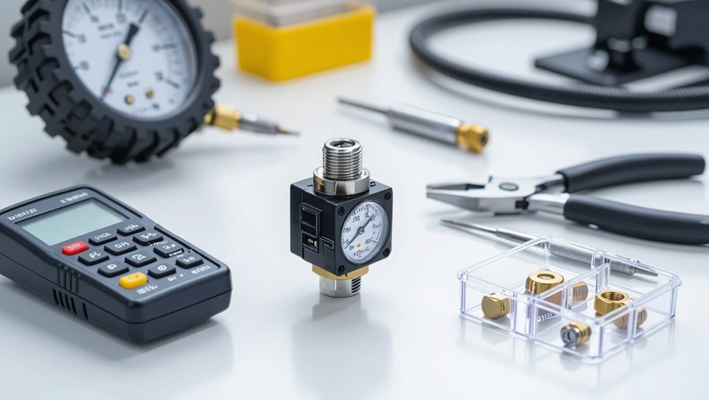
Common signs of a failing pressure switch include irregular cycling, failure to start or stop the pump, visible corrosion, or burnt contacts.
The guide outlines simple DIY checks for obvious issues and explains when professional diagnosis is safer and more effective.
Safety precautions such as disconnecting power, releasing system pressure, and using proper protective gear are emphasized before any testing.
Common signs that indicate a faulty pressure switch
Several clear symptoms can point to a failing pressure switch on a pump or HVAC system.
Frequent cycling, failure to start or stop, inconsistent pressure readings, visible corrosion or moisture, and electrical arcing or burning smells are common clues.
Difficulty maintaining set pressure, erratic system behavior, or blown fuses also suggest a problem.
Observing these helps determine how to tell if pressure switch is bad.
When to call a professional versus DIY checks
When should a homeowner attempt basic diagnostics and when is a technician required?
Homeowners may perform simple checks: visual inspection, listening for clicks, verifying power and loose connections, and testing continuity if comfortable.
Call a licensed technician for pressure gauge replacement, sealed-system access, persistent intermittent faults, electrical hazards, complex controls, or when drainage, pumps, or warranty considerations demand professional diagnosis and repair.
Safety precautions before testing a pressure switch
Before attempting any tests, a homeowner should prioritize safety by de-energizing the system, isolating power at the breaker, and confirming no residual voltage with a reliable tester.
Personal protective equipment (insulated gloves and eye protection) and clear workspace access reduce the risk of shock and accidental contact.
Additionally, lockout/tagout, proper lighting, nonconductive tools, and avoiding wet conditions protect equipment and prevent injury.
Pressure Switch Basics and How It Works
A pressure switch controls when a pump or HVAC component turns on and off by sensing fluid or air pressure and opening or closing an electrical contact at set points.
They range from simple single-pole mechanical switches for residential pumps to electronic or diaphragm-based models used in commercial HVAC and safety systems, each suited to different pressure ranges and response needs.
Understanding the switch’s diaphragm or piston, adjustable setpoint and differential, and the contact behavior under load is essential for diagnosing electrical and pressure-related faults.
What a pressure switch does in pumps and HVAC systems
Pressure switches act as automatic on-off controls that monitor system pressure and open or close electrical contacts to start or stop pumps and HVAC compressors.
They maintain desired pressure range by signaling equipment when preset thresholds are reached, preventing overpressure or dry-run.
They also protect motors and systems by triggering shutdowns, enabling restart cycles, and coordinating with safety and control circuits for reliable operation.
Types of pressure switches and typical applications
Several common designs address different sensing needs and environments: mechanical diaphragm, piston, and bellows switches for liquid and gas service; snap-acting microswitches for fast cycling; and electronic solid-state units that offer adjustable setpoints and repeatable precision.
- Industrial hydraulic and compressor protection.
- HVAC and boiler pressure control.
- Domestic water pumps and safety cutouts.
Key components and electrical behavior to understand
Understanding how a pressure switch operates requires recognizing its two core domains: the sensing element that converts fluid pressure into mechanical motion, and the electrical contacts that open or close circuits in response.
The sensing element (diaphragm, piston, or bellows) transfers motion to a spring-adjusted lever. Contacts change state at setpoints, often with hysteresis; wiring, terminals, and insulation affect reliability and diagnostics.
9 Diagnostic Tests to Determine a Bad Pressure Switch
A systematic approach helps isolate whether a pressure switch is failing.
Start with a visual inspection for corrosion, physical damage, and leaks. Then use a multimeter to confirm power and continuity.
Follow by manually changing pressure to observe activation. Check the tubing and diaphragm for blockages or wear, and verify cut-in/cut-out settings and calibration.
Visual inspection for corrosion, damage, and leaks
When inspecting a pressure switch, begin with a careful visual survey to identify corrosion, physical damage, or signs of fluid leakage that could compromise operation.
Examine terminals, housing, and diaphragm area for rust, cracked plastic, bent connectors, or mineral deposits.
Note wetness, staining, or crystallized residue indicating slow leaks.
Photograph findings, record locations, and replace or service affected components as warranted.
Check for power and continuity with a multimeter
Before applying power, the technician verifies correct wiring and safety precautions. Then, they use a multimeter to check for incoming voltage at the switch and continuity across its terminals while cycling the system. This confirms whether the switch receives power and whether its internal contacts open and close as expected.
Record voltage readings, compare to specifications, and note intermittent or absent continuity indicating a faulty switch or wiring fault.
Test switch activation by manually changing pressure
To verify the switch’s responsiveness, the technician manually alters system pressure while observing switch operation and corresponding electrical continuity or control signals.
Incremental pressure changes guarantee the switch trips at expected setpoints; recordings compare actual activation to specifications.
Note any hesitation, chatter, or failure to change state. If the switch does not respond properly, replacement or calibration is indicated.
Inspect the pressure tubing and diaphragm for blockages or wear
Following verification of switch actuation and electrical response, attention shifts to the mechanical pathways that convey pressure: the tubing and diaphragm.
Inspect tubing for cracks, kinks, blockages, and secure fittings. Remove and visually examine the diaphragm for brittleness, tears, or deformation.
Clean ports gently, replace compromised tubing or diaphragm, and retest switch operation to confirm restoration of reliable pressure transmission.
Verify cut-in and cut-out pressure settings and calibration
Begin by confirming the pressure switch’s cut-in and cut-out points with a calibrated gauge and a controlled pressure source.
Record actual activation and deactivation pressures, compare to nameplate specifications, and note hysteresis.
Adjust adjustment nuts or screws per manufacturer instructions if readings deviate.
If calibration cannot be achieved or readings fluctuate unpredictably, replace the switch to restore reliable pressure control.
Test for rapid cycling or short-cycling symptoms
Why is the pump cycling on and off more frequently than expected?
Inspect for short-cycling by recording cycle frequency over several minutes. Check for rapid pressure drops indicating leaks, compromised check valve, waterlogged tank, or incorrect cut-in/out spread.
Temporarily isolating sections helps locate source. Excessive cycles suggest switch diaphragm wear or contact sticking; replace if mechanical faults are confirmed.
Listen for clicking or electrical arcing during operation
After checking for short‑cycling, attention should turn to audible clues that indicate electrical problems at the pressure switch.
A steady or intermittent click when the pump cycles can signal worn contacts or loose terminals.
Sharp zaps or sizzling suggest arcing inside the switch. These sounds warrant immediate inspection and power isolation; persistent arcing indicates replacement to prevent thermal damage or fire risk.
Check for moisture, dirt, or mineral buildup affecting contacts
Moisture, dirt, and mineral deposits are common culprits that impair pressure switch contacts by creating conductive paths or insulating layers that prevent reliable arcing and mechanical closure.
Inspect the contacts visually after power isolation; use a soft brush, contact cleaner, or distilled water rinse for mineral scale, then dry thoroughly.
Corroded or pitted contacts require light deoxidation or replacement to restore proper operation.
Swap with a known-good switch or bench-test on a test rig
Swap the suspect unit with a known-good pressure switch or bench-test it on a controlled rig to isolate electrical or mechanical faults that inspection alone might miss.
Disconnect power, note terminal wiring, and fit the replacement to verify system behavior under load.
For bench tests, apply adjustable pressure and monitor continuity, setpoint, hysteresis, and contact integrity.
Record results and restore correct component if failure reproduces.
Step-by-Step How to Perform Each Diagnostic Test
Before beginning, the technician gathers required tools and follows safety precautions to isolate power and relieve system pressure.
The following sections provide concise, step-by-step procedures for a visual inspection, multimeter tests for continuity and voltage, controlled pressure manipulation to observe switch response, and safe access to internal components.
Each procedure emphasizes clear actions, expected readings, and decision points for repair or replacement.
Preparing tools and ensuring safety
Gather the necessary tools and confirm safety protocols before performing any diagnostic test on a pressure switch.
The technician assembles insulated screwdrivers, multimeter, pressure gauge, replacement terminals, and PPE (gloves, safety glasses).
Power sources are isolated and locked out; system pressure is relieved.
Documentation and manufacturer specs are reviewed.
A nonconductive work surface and proper lighting are prepared to guarantee accurate, safe testing.
Step-by-step: visual inspection checklist
One concise visual inspection covers exterior condition, mounting integrity, electrical connections, and signs of wear or contamination before any electrical or pressure tests begin.
- Check for cracks, corrosion, oil, or debris on the housing and diaphragm area.
- Verify mounting bolts, seals, and alignment are secure and undamaged.
- Inspect wire insulation, terminal tightness, and any discoloration indicating overheating or moisture ingress.
Step-by-step: using a multimeter to test continuity and voltage
Begin by ensuring the system is de-energized and the pressure source is stable; safety and a known baseline condition are essential before probing electrical contacts.
Set the multimeter to continuity, check terminals for open/closed states at rest.
Re-energize if safe, measure voltage to verify supply and switched output.
Record readings, compare to specifications, and document anomalies for repair or replacement.
Step-by-step: safely inducing pressure changes to observe switch response
Several controlled pressure changes should be applied while observing the switch to confirm trip and reset behavior under real conditions.
Begin at zero or baseline pressure, slowly increase to the switch’s cut-in value, note actuation, then raise to cut-out if applicable.
Decrease pressure steadily, confirm reset point and hysteresis.
Repeat cycles, record inconsistencies, and cease testing if leaks or unsafe readings occur.
Step-by-step: accessing and inspecting internal components
Before opening the switch enclosure, gather the required tools—insulated screwdrivers, multimeter, small flashlight, needle-nose pliers, and safety gloves—and verify that power and pressure sources are fully isolated and locked out.
Remove cover screws, note gasket condition, and inspect diaphragm, spring, and contact assembly for wear, corrosion, or debris.
Clean contacts gently, check terminal tightness, and document visible damage for repair or replacement.
Step-by-step: recording cut-in/cut-out pressures and interpreting results
One clear way to confirm a pressure switch’s performance is to record its cut-in and cut-out pressures under controlled conditions; this requires a reliable pressure gauge, a multimeter (to detect switching), and a method to slowly vary system pressure while observing the switch.
Attach gauge, monitor multimeter continuity, raise pressure until contacts open (cut-out) and lower until they close (cut-in).
Compare against specs; deviations indicate adjustment need or replacement.
Common Causes of Pressure Switch Failure and How to Spot Them
Common pressure switch failures stem from mechanical wear such as diaphragm tears, electrical contact pitting or corrosion, and clogged sensing ports or tubing.
Incorrect settings or mechanical misadjustment also compromise operation, while environmental factors like moisture, extreme temperatures, and vibration accelerate deterioration.
Recognizing these signs—visible diaphragm damage, burnt or corroded contacts, blocked ports, misaligned adjustments, or evidence of exposure—helps pinpoint the root cause quickly.
Mechanical wear and diaphragm failure
Many pressure switch failures trace back to mechanical wear and diaphragm deterioration, which gradually undermine the device’s ability to sense and respond to pressure changes.
Worn springs, stretched linkages, or ruptured diaphragms cause drift, sticking, or failure to actuate.
Visual inspection reveals cracks or deformation; functional tests show inconsistent cut-in/cut-out points.
Replace fatigued components to restore reliable operation.
Electrical contact pitting and corrosion
Electrical degradation undermines a pressure switch’s electrical performance when contacts pit or corrode, interrupting reliable circuit closure and causing intermittent operation or outright failure.
Inspect terminals and contact faces for dark spots, roughness, or green/white corrosion. Measure continuity under load and look for arcing evidence.
Clean or replace contacts, tighten connections, and guarantee proper environmental sealing to prevent recurrence.
Clogged sensing ports and tubing
While pitted or corroded contacts interrupt electrical continuity, mechanical obstructions in a switch’s sensing pathway can equally compromise performance.
Debris, sediment, mineral buildup, or collapsed tubing can block pressure ports, causing delayed, erratic, or absent switching. Inspect and blow out ports, replace brittle tubing, and clean fittings.
Regular maintenance prevents buildup; replace components if cleaning fails or damage is evident.
Incorrect settings or mechanical misadjustment
Incorrect pressure settings or mechanical misadjustments frequently prevent a switch from operating at the desired setpoints, causing systems to cycle improperly or fail to respond.
Technicians should verify cut-in/cut-out settings, spring tension, and range stops against specifications.
Simple calibration errors, loose adjustment screws, or improper replacement parts can shift activation thresholds; correcting these restores reliable operation without replacing the switch.
Environmental factors: moisture, temperature, and vibration
Beyond misadjustment, external environmental conditions often degrade pressure switch performance in ways that mimic calibration faults.
Moisture causes corrosion and shorts; condensation fouls contacts.
Extreme temperatures alter spring tension and diaphragm elasticity, shifting set points.
Continuous vibration loosens terminals, fractures solder joints, and wears mechanical linkages.
Inspect for corrosion, water ingress, thermal exposure, and mounting integrity; document environmental history during diagnosis.
How to Fix a Faulty Pressure Switch: Repair vs Replacement
The section outlines simple, safe repairs homeowners can perform—cleaning contacts, tightening connections, and recalibrating settings—before considering replacement.
It then explains when a switch should be replaced, how to choose a compatible model, and provides a clear step‑by‑step replacement and wiring guide.
Typical cost and time estimates for DIY versus professional service are included to help decide the most practical option.
Simple fixes you can safely perform (cleaning, tightening, recalibrating)
Start by addressing the easiest, lowest-risk steps before deciding on replacement: many pressure switch issues stem from dirt, loose connections, or slight calibration drift that can be corrected with basic tools and safety precautions.
Recommended steps:
- Clean contacts and ports with contact cleaner; remove debris.
- Tighten terminal screws and fittings; secure grounding.
- Recalibrate setpoints per manufacturer instructions; test under load.
When to replace the switch and how to select the right model
When should a pressure switch be replaced rather than repaired? Replacement is advised if corrosion, persistent electrical arcing, sealed diaphragm failure, or frequent repeat faults occur.
Selection criteria should match system pressure range, electrical ratings, contact type, and enclosure rating.
- Safety: certified ratings and compatibility
- Performance: pressure setpoints and hysteresis
- Longevity: materials and environmental protection
Step-by-step replacement procedure and wiring tips
Begin by isolating power and relieving system pressure to guarantee safe access to the switch. Once verified, remove the cover, document wiring positions, and photograph connections for reference before disconnecting wires and unfastening the switch from its mounting.
Install the matched replacement, reattach wires to original terminals, and tighten fittings. Restore pressure slowly while checking for leaks, and reapply power to verify proper operation.
Typical costs and time estimates for DIY vs professional service
After completing the isolation, documentation, and replacement steps, a cost-and-time comparison helps decide between a DIY fix and hiring a professional. DIY parts: $20–$80, 1–2 hours. Pro service: $150–$400, 1–3 hours. Consider warranty, safety, and complexity when choosing.
| Option | Typical range |
|---|---|
| Parts (DIY) | $20–$80 |
| Time (DIY) | 1–2 hours |
| Professional | $150–$400 |
Preventive Maintenance to Extend Pressure Switch Life
A routine preventive maintenance program can greatly extend a pressure switch’s service life by combining a regular inspection schedule with a concise maintenance checklist.
Proper installation, environmental controls, and adherence to best practices reduce mechanical stress and contamination risks.
Scheduled calibration intervals with clear record-keeping guarantee accuracy and provide traceable maintenance history.
Regular inspection schedule and maintenance checklist
When equipment downtime carries operational and safety consequences, a concise regular inspection schedule paired with a focused maintenance checklist guarantees pressure switches remain reliable and serviceable.
Inspections should be routine, documented, and tailored to the application’s duty cycle and environmental stresses.
- Monthly: visual, wiring, and actuator linkage checks.
- Quarterly: contact resistance, insulation, and calibration verification.
- Annual: full cleaning, diaphragm/port replacement, and record audit.
Best practices for installation and environment control
Several key installation and environmental controls directly influence pressure switch longevity and reliability.
Mounting must be vibration-isolated, level, and oriented per manufacturer instructions. Use proper fittings, avoid over-tightening, and install filters or dampeners to prevent pulsation and particulate ingress.
Maintain ambient temperature and humidity within specified ranges, provide corrosion protection, and guarantee electrical connections are secure and strain-relieved to prevent premature failure.
Calibration frequency and record-keeping tips
Regularly scheduled calibration and meticulous record-keeping are essential to detect drift, verify setpoint accuracy, and document actuator and contact wear trends over time.
Recommended calibration intervals vary with duty cycle, criticality, and manufacturer’s guidance—typically quarterly to annually. Log date, technician, methods, reference standards, measured setpoints, adjustments, and serial numbers.
Review records for trends, trigger corrective action thresholds, and retain documentation per compliance requirements.
Troubleshooting Scenarios and Solutions
The troubleshooting section presents diagnostic paths for common faults: a system that refuses to start, one that won’t stop or is short-cycling, and intermittent failures.
For each scenario, it outlines likely causes and step-by-step checks to narrow whether the issue is electrical, mechanical, or control-related.
Clear corrective actions and tests are provided to guide repair or further professional evaluation.
System won’t start diagnostic path and likely causes
Begin troubleshooting by confirming that power is present at the control panel and that safety interlocks and upstream components are not preventing startup.
Inspect pressure switch continuity and setpoint, check for clogged or closed supply valves, trapped or ruptured sensing lines, and failed pilot devices.
Verify control relay outputs and wiring integrity.
Replace suspect switch only after isolating electrical or plumbing faults.
System won’t stop or short-cycling diagnostic path and fixes
After confirming startup power and ruling out upstream safeguards, attention shifts to conditions where the compressor or pump refuses to stop or cycles rapidly.
Inspect pressure switch contacts for pitting, verify correct cut-out and differential settings, check for stuck diaphragm or sensing port blockage, and confirm tank/receiver integrity and leak presence.
Replace faulty switch or repair leaks to restore normal cycling.
Intermittent failures how to isolate electrical vs mechanical issues
How can a technician distinguish between electrical glitches and mechanical faults when a pressure switch fails sporadically?
The technician logs failure timing, inspects wiring and terminals for corrosion or loose connections, and uses a multimeter to monitor contact continuity during events.
Mechanical checks include cycling the diaphragm and checking for debris or wear.
Reproducing the fault under controlled pressure separates causes.
Tools, Parts, and Resources You’ll Need
A concise list of tools and parts helps guarantee safe and accurate testing and replacement of a pressure switch.
Recommended items include a multimeter, adjustable wrench, insulated screwdrivers, replacement diaphragms or switch assemblies with matching pressure and electrical specs, and appropriate sealing supplies.
Reference diagrams, manufacturer manuals, and reputable online guides are advised for correct identification and procedure.
Recommended tools for testing and replacement
Gathering the right tools and parts before testing or replacing a pressure switch streamlines the job and reduces errors.
Essential recommended tools include multimeter for continuity/voltage checks, adjustable wrench and nut driver set for removal, and pressure gauge for accurate readings.
Additional items: thread sealant, insulated screwdrivers, safety glasses.
Prioritize calibrated tools and correct sizes for safe, accurate work.
- Multimeter
- Wrench set
- Pressure gauge
Common replacement parts and specifications to match
Several key replacement parts should be identified and matched by specification before beginning work on a pressure switch.
Common parts include the switch unit with matching pressure range and cut-in/cut-out settings, compatible electrical contact type (SPST/SPDT), appropriate terminal and wire gauge ratings, pressure port fittings and thread sizes, diaphragm or bellows material compatible with fluid, and suitable mounting hardware and gasket materials.
Helpful diagrams, manuals, and online resources
One clear wiring diagram, the manufacturer’s instruction manual, and a pressure-range chart provide the core references technicians should consult before servicing or replacing a pressure switch.
Essential online resources include factory PDFs, circuit schematics, and OEM part cross-references. Verify model numbers and safety ratings.
Recommended items:
- Manufacturer manual and schematic
- Pressure-range/spec sheet
- OEM parts and wiring diagrams
Safety Checklist and Final Verification After Repair
A concise safety checklist and final verification procedure guarantees the pressure switch and system are returned to reliable operation.
Technicians should perform final electrical and pressure tests, follow step-by-step safety steps to restore the system to normal use, and verify all connections and guards are secure.
After repair, monitor specific signs—pressure stability, cycling behavior, and any abnormal noises or leaks—to confirm long-term reliability.
Final electrical and pressure tests to confirm proper operation
Begin the final verification by isolating the system, restoring power, and performing measured electrical and pressure checks to confirm the pressure switch and associated components operate within specified parameters.
Verify voltage at switch terminals, confirm continuity across contacts during actuation, and monitor cut-in/cut-out pressures with a calibrated gauge.
Record results, compare to manufacturer specs, and only proceed if all readings fall within tolerance.
Safety steps to restore system to normal use
After completing electrical and pressure checks and confirming readings align with manufacturer specifications, proceed with a concise safety checklist before returning the system to service.
Verify all covers, guards, and conduit are secured; confirm valves and isolation points operate correctly; restore power following lockout/tagout procedures; check for leaks, unusual noises, or vibration; document repairs and test results; notify stakeholders and resume normal operation.
Signs to monitor after repair to ensure long-term reliability
When repairs are complete, operators should monitor a concise set of indicators over the following weeks to confirm the pressure switch and system remain reliable: log pressure stability, cycle frequency, and response time; inspect for leaks, corrosion, or wiring degradation; verify setpoint retention and calibration; record alarm occurrences and false trips; confirm thermal and vibration conditions remain within specifications; schedule follow-up checks and document findings for trend analysis.
Conclusion
In conclusion, the guide leaves the reader with clear tests and fixes to judge a pressure switch’s health: check power, continuity, tubing, contacts, and settings, and replace or clean as needed. Like a clockmaker consulting both sundial and stopwatch, the technician combines old instincts with modern meters to diagnose faults efficiently. With routine maintenance and safety checks, recurring failures are minimized and system reliability restored, closing the repair loop.