How to Fix Temperature Sensor Failure on a Water Heater: Step-by-Step Troubleshooting and Repair
To fix a faulty water heater temperature sensor, start by shutting off the power and water supply. Inspect the sensor’s probe and wiring for signs of corrosion or damage. Use a multimeter to check continuity and resistance, making sure to rule out issues with thermostats and heating elements. If the sensor is damaged, replace it with a new one, ensuring proper sealing and wiring connections. After restoring power, verify the sensor’s output with a thermometer and adjust settings as necessary. For further guidance, continue with detailed troubleshooting, calibration, and safety tips.
What Causes a Water Heater Temperature Sensor to Fail
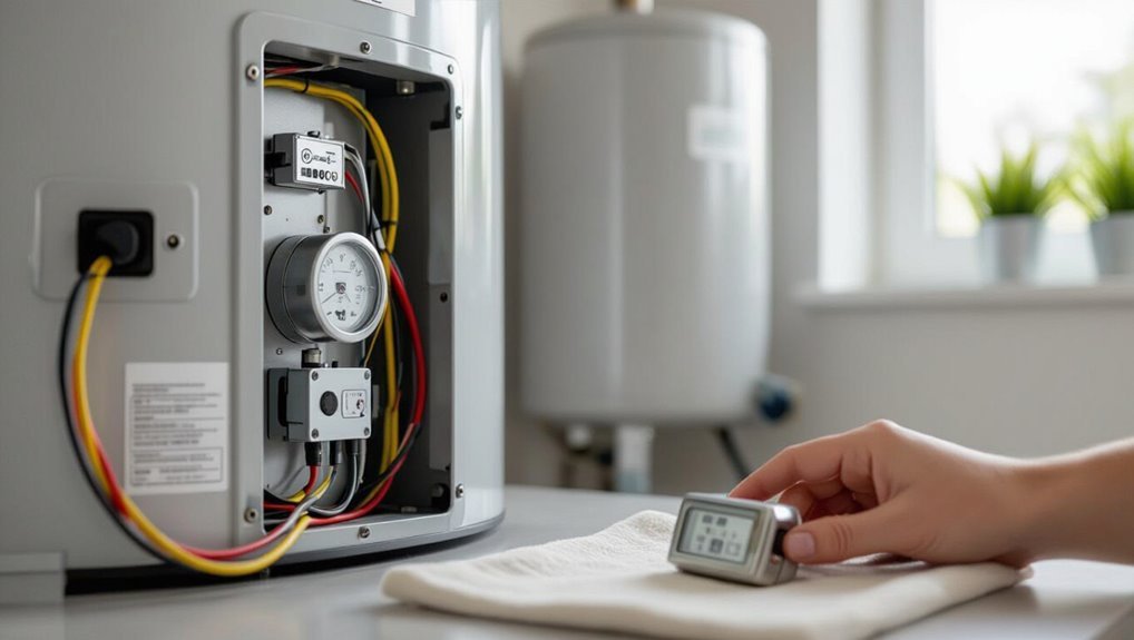
Temperature sensor failures typically stem from mechanical wear or electrical faults such as broken elements, shorted wiring, or connector corrosion.
Environmental and installation factors—hard water, sediment buildup, high ambient temperatures, or improper mounting—accelerate deterioration and stress on the sensor.
Distinguishing sensor degradation from other component issues requires noting specific signs like erratic temperature readings, slow response, or open-circuit readings versus symptoms of thermostat, heating element, or control board failure.
Common mechanical and electrical failure modes
Several factors commonly contribute to a water heater temperature sensor failing, including corrosion from mineral-laden water, mechanical damage from physical impact or vibration, electrical faults such as short circuits or open connections, and degradation of sensor elements from prolonged high-temperature exposure.
Typical failure modes include broken leads, intermittent contacts, insulation breakdown, and resistor drift.
Troubleshooting guides for how to fix temperature sensor failure water heater focus on inspection, testing, and targeted replacement.
Environmental and installation factors that shorten sensor life
Although exposure alone does not always cause immediate failure, environmental and installation conditions markedly shorten the lifespan of a water heater’s temperature sensor.
Corrosive water chemistry, mineral scaling, and high humidity promote corrosion and insulation breakdown.
Poor mounting, vibration, inappropriate immersion depth, and electrical overstress from nearby wiring increase mechanical and thermal fatigue.
Inadequate sealing permits moisture ingress and accelerates failure.
Signs and symptoms of sensor degradation vs other component failures
Environmental and installation stresses that erode a sensor’s materials and connections often produce warning signs that differ from failures in thermostats, heating elements, or control boards.
Sensor degradation yields intermittent temperature reading drift, slow response, or erratic setpoint changes without physical element noise.
Other component failures cause constant overheating/underheating, tripped breakers, visible corrosion, or audible element humming.
Accurate diagnosis requires multimeter checks and process of elimination.
How to Confirm the Temperature Sensor Is the Problem
Before testing, the technician confirms power and water are shut off and wears appropriate protective gear to prevent shock or scalding.
A visual inspection of the sensor, connectors, and wiring follows, then a multimeter is used to check continuity and resistance against expected values at known temperatures.
Finally, the technician rules out related components—thermostats, heating elements, control boards, and wiring—before concluding the sensor is at fault.
Safety precautions before inspecting a water heater
Any inspection of a water heater’s temperature sensor should begin with strict safety measures to prevent electrical shock, scalding, or accidental damage.
Verify power is fully disconnected at the breaker and label it. Allow the tank to cool and relieve pressure by opening a hot faucet briefly.
Wear insulated gloves and eye protection. Keep the area dry and well-ventilated. Use nonconductive tools.
Visual inspection checklist for sensors and wiring
With power off and the tank cooled, the inspector should begin a focused visual check of the temperature sensor and its wiring to determine whether the sensor is the source of the fault.
Inspect for loose or corroded connectors, frayed insulation, burn marks, moisture intrusion, or physical damage to the probe.
Verify secure mounting and correct routing; note any aftermarket splices or non-standard components.
Using a multimeter to test sensor continuity and resistance
Begin by powering down the heater and confirming the tank is cool.
Then use a digital multimeter to check the sensor’s electrical continuity and resistance so the inspector can determine whether the probe itself is faulty.
Disconnect the sensor, set the meter to continuity or resistance, probe terminals, note open circuit or erratic readings, and document measurements for comparison during final diagnosis.
Interpreting temperature readings and expected resistance values
Compare the meter’s resistance readings to the sensor’s specified values at known temperatures to determine whether the probe is failing. Record readings at ambient, warm, and hot points; compare against the manufacturer chart. Significant deviation or non-linear change indicates a bad sensor needing replacement.
| Temperature | Expected Ω |
|---|---|
| Ambient | 10,000 |
| Hot | 2,000 |
Rule-out checklist: thermostats, heating elements, control boards, and wiring
After confirming that the sensor’s resistance readings deviate from the manufacturer’s chart, technicians should systematically eliminate other components that can mimic sensor failure: thermostats, heating elements, control boards, and wiring.
Inspect thermostats for calibration and continuity, test elements for shorts or open circuits, verify control board diagnostics and error codes, and check wiring and connectors for corrosion, breaks, or poor crimps before replacing the sensor.
Step-by-Step Guide to Replacing a Faulty Temperature Sensor
The following steps outline the practical replacement of a failed water heater temperature sensor, beginning with assembling the necessary tools and replacement parts.
The procedure covers preparatory safety measures—disconnecting power, shutting off the water supply, and relieving tank pressure—then locating and accessing the control compartment to remove the old sensor.
Finally, it describes installing, securing, and testing the new sensor to restore proper operation.
Tools and parts you’ll need
Before starting the replacement, gather the essential tools and parts so the job proceeds efficiently and safely.
A technician prepares a compact kit to remove and install the sensor, test electrical connections, and seal fittings. Quality parts and basic hand tools minimize delays and leaks.
- Multimeter (for continuity and voltage)
- Replacement temperature sensor compatible with model
- Nut driver and adjustable wrench
- Teflon tape and silicone sealant
- Insulated screwdriver set
Preparing the unit: power, water supply, and pressure relief steps
With tools and parts assembled, the technician moves on to prepare the water heater by cutting power, shutting off the water supply, and relieving tank pressure to create a safe work environment.
They verify power is off at the breaker, close the cold-water inlet, open a hot faucet to drain slight pressure, and attach a hose to the drain valve to remove remaining water before proceeding.
Locating the sensor and accessing the control compartment
Locate the temperature sensor by referencing the heater’s schematic or manual to identify its typical mounting—usually on the upper tank or near the thermostat housing—and note any wiring routes and connector types before opening the control compartment.
Remove exterior access panel fasteners, set panels aside, and inspect internal layout. Photograph connections, label wires, and verify clearance, lighting, and tool access prior to further work.
Removing the old sensor safely
Having documented the wiring and opened the control compartment, the technician proceeds to remove the faulty temperature sensor following a methodical safety routine.
Power remains isolated and capacitors discharged. Insulation and gloves protect against burns.
Connectors are detached with correct tools, noting orientation. Mounting fasteners are loosened, sensor extracted gently to avoid damage to the probe or tank fittings, then placed in a labeled container.
Installing and securing the new sensor
Begin by inspecting the new sensor and matching it against the removed unit for size, probe length, thread pitch, and connector type to verify compatibility before any installation steps commence.
Position the sensor into the mounting port, hand-thread to avoid cross-threading, then tighten with the appropriate wrench to specified torque.
Verify the probe seats fully and the mounting surface is clean and flat.
Reconnecting wiring and seals to manufacturer specs
Reconnect wiring and seals strictly according to the manufacturer’s specifications to guarantee correct operation and prevent leaks or electrical faults.
The technician matches wire colors and terminal labels, tightens connections to specified torque, and routes harnesses away from heat or moving parts.
Replace gaskets or O-rings with approved parts, apply recommended sealant sparingly, and verify mechanical compression without distortion before reassembling covers.
Restoring power and performing initial startup
Power is restored only after all wiring and seals have been verified secure and covers are replaced to manufacturer specifications.
The technician reactivates the circuit breaker or restores gas supply, then powers the unit. They observe startup sequences, check for error codes, listen for abnormal sounds, and verify the sensor reports stable temperature.
Final checks include leak inspection and documenting operational readings before closing the service.
How to Calibrate and Verify the New Sensor
After installation, the technician checks the sensor output with a multimeter to confirm proper resistance or voltage readings.
They then compare measured water temperature with an independent thermometer to verify the sensor reflects actual conditions.
Finally, they adjust thermostat settings and any control board parameters as needed to align system behavior with the verified sensor readings.
Checking sensor output with a multimeter after installation
Use a digital multimeter to confirm the new temperature sensor is producing the expected signal before completing reassembly.
Set the meter to the correct mode (ohms for thermistors, millivolts for thermocouples).
Compare readings to the sensor’s specification table at known reference points.
Verify stable, noise-free output while gently varying temperature.
Record values and reinstall if within tolerance; replace if not.
Confirming accurate water temperature with a thermometer
A calibrated handheld thermometer provides an independent reference to confirm the water heater’s sensor accuracy and should be used to cross-check readings at multiple setpoints.
Place the thermometer probe in a stable hot-water stream or tank sample, allow temperature to stabilize, and compare values to the sensor output.
Repeat at low, mid, and high points; document discrepancies and sensor tolerances for verification.
Adjusting thermostat settings and control board parameters
With verified thermometer readings in hand, the technician proceeds to calibrate the replacement sensor by adjusting thermostat setpoints and related control-board parameters to match the reference values.
They enter service mode, modify offset or gain values, set hysteresis and safety limits, then save settings.
Verification follows: stabilize heater, compare temperatures, iterate adjustments until measured and setpoint temperatures concur within acceptable tolerance.
Troubleshooting When Replacement Doesn’t Fix the Issue
If replacing the temperature sensor does not resolve erratic readings, attention should shift to diagnosing intermittent signals and testing related components such as thermostats, heating elements, and the control board.
The wiring harness and connectors must be inspected for corrosion, loose terminals, or intermittent shorts that can mimic sensor failure.
Persistent faults, repeated error codes, or evidence of control board damage indicate the need for professional service or full control module replacement.
Diagnosing intermittent or inaccurate readings
When replacement sensors continue to produce intermittent or inaccurate readings, the problem often lies beyond the sensor itself—manifesting in wiring faults, control board issues, or environmental interference.
Inspect wire harnesses for corrosion, breaks, loose connectors and proper shielding. Check routing away from heat sources and electrical noise.
Verify stable power and grounding. Document patterns, conditions, and timing to correlate faults with external factors.
Testing related components: thermostats, elements, and control boards
Having ruled out sensor faults and wiring anomalies, attention shifts to other system components that can produce similar symptoms: thermostats, heating elements, and control boards.
Technicians test thermostats for setpoint accuracy and continuity, measure element resistance and ground faults, and scan control boards for error codes, burnt traces, or failed relays.
Replace or repair only after isolating the defective component.
When wiring or connectors are the root cause
Begin by tracing the entire signal path from the sensor to the control module, because intermittent faults often live in connectors, splices, or chafed insulation rather than in the replacement parts themselves.
Inspect harnesses for corrosion, bent pins, burnt insulation, and loose terminals.
Wiggle-test connections under power (safely) and continuity-check wires.
Repair or replace damaged connectors, reseal junctions, and secure wiring away from heat or vibration.
Signs you need professional service or full control module replacement
If careful tracing and connector repairs fail to restore reliable temperature readings, the problem may lie beyond simple wiring or a single sensor swap.
Persistent erratic readings, repeated error codes, or sensors that test within tolerance yet produce faults indicate control module failure.
Also watch intermittent heater cycling, unexplained overheating, or failed self-tests; these warrant professional diagnostics and likely full control board replacement.
Choosing the Right Replacement Sensor
Selecting a replacement sensor starts with identifying the sensor type—thermistor, RTD, or thermocouple—and confirming electrical and temperature range compatibility.
The choice between OEM and aftermarket options should weigh cost, warranty, and proven fit with the specific water heater model.
Exact part numbers and specification sheets must be matched to guarantee proper function and safe operation.
Understanding sensor types and compatibility (thermistors, RTDs, thermocouples)
What distinguishes thermistors, RTDs, and thermocouples is their sensing principle, temperature range, accuracy, and the way they interface with the water heater’s control electronics.
Thermistors offer high sensitivity over limited ranges; RTDs provide stability and accuracy across wider ranges; thermocouples endure high temperatures and fast response.
Compatibility requires matching output type, resistance/voltage characteristics, connector, and mounting for correct control integration.
OEM vs aftermarket sensors: pros and cons
After comparing thermistors, RTDs, and thermocouples for electrical characteristics and mounting, the next decision is whether to replace a failed sensor with an OEM part or an aftermarket unit. OEMs guarantee exact fit and warranty alignment; aftermarket options can lower cost and offer broader availability but vary in quality. Choose based on reliability, compatibility, and budget.
| Option | Pros | Cons |
|---|---|---|
| OEM | Fit, warranty | Higher cost |
| Aftermarket | Lower price | Variable quality |
| Generic | Widely available | May need adaptation |
Reading part numbers and matching specifications
Begin by locating the stamped or printed part number on the failed sensor or its packaging.
Cross-reference that number with the heater’s manual and manufacturer website to confirm compatibility.
Check electrical ratings, resistance curve (e.g., NTC/PTC), length, connector type, and mounting style.
If exact match unavailable, select equivalents with identical specs to guarantee accurate temperature reading and safe operation.
Preventive Maintenance to Extend Sensor Life
A regular inspection schedule helps identify early signs of sensor wear—loose connections, buildup, or erratic readings—so checks should be noted and acted on.
Water quality management, timely anode rod replacement, and corrosion control reduce electrochemical damage that shortens sensor life.
Correct installation practices, including secure fittings and proper routing, minimize mechanical stress and wiring faults that lead to premature failure.
Routine inspection schedule and what to look for
Regular inspections create a predictable rhythm that prevents small issues from becoming sensor failures. Technicians should establish a quarterly check for residential systems and a monthly check for commercial units with higher usage.
Inspections focus on sensor mounting, wiring integrity, connector cleanliness, insulation condition, and system response tests.
- Confirm secure sensor mounting
- Inspect wiring for frays or corrosion
- Check connector cleanliness
- Verify insulation integrity
- Perform calibrated response test
Water quality, anode rods, and corrosion control
Monitor water chemistry and maintain sacrificial anode rods to minimize corrosion that degrades sensor housings and wiring connections; high chloride levels, low pH, and hard-water scale accelerate metal loss and electrical failures.
Regularly test for chlorides, pH, and hardness, replace depleted anodes, and flush tanks to remove sediment.
Consider corrosion inhibitors or water softening where appropriate to extend sensor and tank life.
Proper installation practices to avoid future failures
Following attention to water chemistry and anode maintenance, correct sensor performance also depends on proper installation practices that prevent mechanical stress, electrical faults, and exposure to corrosive elements.
Technicians should mount sensors securely, avoid bending or compressing probes, use correct fittings and dielectric unions, route wiring away from heat and moisture, apply appropriate sealants, and verify electrical connections and grounding to guarantee stable long-term operation.
Cost Estimates and Time Required
Typical part and labor cost ranges for DIY versus professional repairs are summarized to help readers weigh savings against warranty and safety considerations.
Estimated times for diagnosis and replacement are given for common heater types—tank, tankless, and electric—so readers can plan the job or service call.
These figures provide a practical baseline for budgeting both money and time.
Typical part and labor cost ranges for DIY vs professional repair
A basic replacement of a water heater temperature sensor can range from a low-cost DIY job—parts only—to a higher-priced professional service that includes labor, diagnostics, and possible additional parts; homeowners should expect significant differences in both expense and time depending on skill level and system type.
| Repair Type | Parts Cost | Labor Cost |
|---|---|---|
| DIY | $10–$60 | $0 |
| Professional | $30–$150 | $75–$300 |
Estimated time for diagnosis and replacement for common heater types
How long will it take to diagnose and replace a failed temperature sensor on different water heater types?
Diagnosis typically requires 15–45 minutes: tankless units often need 30–45 minutes due to access and error-code checks; tank heaters usually 15–30 minutes.
Replacement ranges 30–90 minutes: DIY on tanks can be 30–60 minutes; professionals for tankless or complex systems may need 60–90 minutes.
Safety Warnings and When to Call a Professional
The section outlines key electrical hazards and scalding risks associated with troubleshooting a temperature sensor on a water heater.
It specifies scenarios—such as exposed wiring, persistent leaks, or circuit faults—when a licensed plumber or electrician should be called.
A concise checklist of model details, observed symptoms, and recent repairs to provide to the technician is recommended to speed up service.
Electrical and scalding risks to be aware of
Many incidents involving water heater sensor failures stem from two primary hazards: electrical shock and scalding.
Exposed wiring, wet components, or improper isolation can energize panels during diagnostics, risking electrocution. Faulty sensors may cause uncontrolled high temperatures, producing scalding water.
Always de-energize equipment, drain or isolate hot outlets, use insulated tools, and wear protective gear to reduce immediate danger.
Situations requiring licensed plumbers or electricians
Given the electrical and scalding dangers outlined above, certain failures should not be handled by homeowners and require licensed plumbers or electricians.
Complex wiring faults, repeated tripping breakers, suspected thermal fuse or heating element defects, gas connections or leaks, corroded tank components, and persistent temperature control failures necessitate professional diagnosis and repair.
Permit-affected work and safety-code compliance must be handled by qualified technicians.
Checklist to provide a technician for faster service
Before the technician arrives, prepare a concise packet of information and observations that will let them diagnose and repair the temperature-sensing issue more quickly and safely.
Gather clear facts, timestamps, and access notes to reduce inspection time and clarify liability.
- Model, serial number, and installation date
- Recent error codes or indicator lights
- Photos of wiring and sensor locations
- Recent maintenance or repairs
- Access, shutoff locations, and safety concerns
Conclusion
Like a lighthouse guiding a storm-tossed ship, a working temperature sensor keeps a water heater steady, warding off scalding waves and icy surprises. When it fails, careful diagnosis, correct replacement, and precise calibration restore balance, while routine checks act as vigilant sailors preventing future drift. If troubles persist beyond these repairs, calling a professional is like summoning an experienced captain—ensuring safety, prolonging the voyage, and preserving comfort in the home’s warm harbor.