How to Check Flame Sensor on Furnace: Step-by-Step Guide for Homeowners
To check your furnace flame sensor, start by cutting off the power and gas supply. Next, remove the access panel to locate the thin metal rod near the burners. Inspect it for any soot, corrosion, or loose wiring. If necessary, gently remove the rod and clean it using fine emery cloth or isopropyl alcohol. After cleaning, reinstall the rod securely, restore power, and observe the ignition process. If you’re still having issues, you can use a multimeter to check for continuity. Follow the step-by-step troubleshooting options provided for further assistance.
How a Furnace Flame Sensor Works and Why It Matters
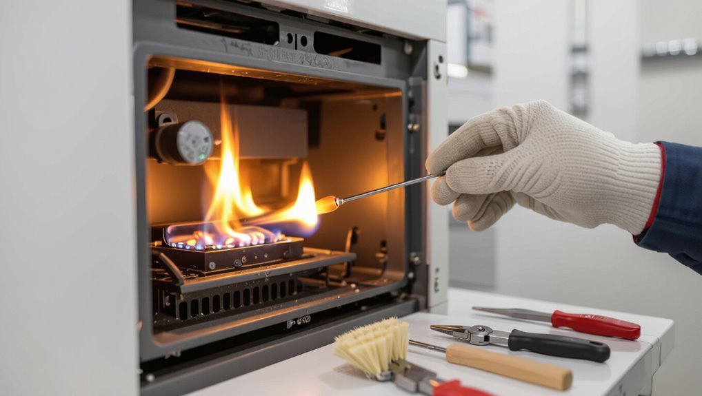
A flame sensor detects whether the burner’s gas ignition produces a stable flame and signals the control board to keep the gas valve open.
When the sensor becomes dirty or fails, the furnace may short-cycle, fail to light, or shut down unpredictably.
Because a faulty sensor can cause incomplete combustion or gas leaks, symptomatic recurring failures or safety concerns should prompt professional service.
Purpose of the flame sensor in a gas furnace
Detects the presence of a sustained gas flame to confirm safe operation and allow the furnace control board to continue the ignition sequence.
The flame sensor prevents unburned gas buildup by signaling when combustion occurs.
Proper understanding of its purpose helps homeowners approach how to check flame sensor on furnace safely and communicate precise observations to technicians, ensuring reliable, code-compliant furnace operation and occupant safety.
Common symptoms of a failing flame sensor
When the flame sensor begins to fail, the furnace often shows predictable signs that indicate impaired flame detection.
Typical symptoms include frequent short cycling, burners that ignite then shut off, repeated ignition attempts, and error codes or flashing LEDs on the control board.
Homeowners may also notice reduced heating efficiency and intermittent operation, signaling the sensor’s declining ability to confirm sustained combustion.
Safety risks and when to call a professional
Those symptoms can escalate into safety hazards if the flame sensor continues to malfunction: a sensor that fails to confirm flame presence may allow unburned gas to accumulate during repeated ignition attempts, increasing the risk of gas leaks or, in rare cases, ignition of accumulated gas.
Immediate professional service is advised for persistent faults, detectable gas odor, repeated lockouts, or inability to safely diagnose and replace the sensor.
Tools and Safety Preparations Before You Begin
Before beginning, the technician should gather basic tools and materials such as a multimeter, small screwdriver, fine-grit sandpaper or emery cloth, and a replacement flame sensor if needed.
They must follow safety precautions: turn off electrical power to the furnace at the breaker and, if applicable, shut off the gas supply before accessing internal components.
If the unit shows signs of gas leaks, persistent ignition problems, or the person is uncomfortable with electrical or gas work, a qualified HVAC professional should be contacted rather than attempting DIY checks.
Required tools and materials
A short list of tools and safety items guarantees the flame sensor check is efficient and safe.
Essential items include a 1/4″ nut driver or screwdriver, fine-grit emery cloth or steel wool, and a multimeter or continuity tester.
Optional: soft brush, replacement sensor, and shop towels.
Visualize the kit:
- Hand tools
- Cleaning media
- Testing device
Safety precautions and power/gas shutoff steps
Several clear safety steps should be followed to prevent injury and equipment damage when checking a furnace flame sensor.
Wear safety glasses and insulated gloves.
Turn off electrical power at the furnace switch and main breaker.
Close the gas valve or the furnace gas shutoff.
Allow components to cool.
Verify power and gas are off with a tester before touching wiring or sensors.
When not to attempt DIY checks
Recognize situations that require professional service rather than DIY checks: if the furnace is under warranty, if the homeowner lacks basic electrical or gas-handling skills, if the flame behavior is erratic or accompanied by smells of gas or soot, or if visible damage, corrosion, or complicated access to the sensor exists.
In such cases, contact a licensed HVAC technician to avoid voiding warranties, safety risks, or further damage.
Locate the Flame Sensor on Common Furnace Types
The flame sensor is typically mounted near the burner assembly, with single-stage units usually having a single rod and two-stage models sometimes showing slightly different placements or multiple sensing components.
Visual appearance can vary by brand—some sensors are slender metal rods while others have protective sleeves or different bracket styles.
Accessing the burner compartment requires shutting power and gas, removing the service panel, and following safe practices to avoid contact with sharp edges or hot surfaces.
Typical placement in single-stage and two-stage furnaces
When inspecting common furnace designs, the flame sensor is usually mounted inside the burner compartment near the main gas burners so it can reliably detect the presence of flame.
In single-stage furnaces, it typically sits adjacent to one burner assembly, centrally placed for consistent sensing.
In two-stage systems, sensors may be positioned to monitor primary and secondary burner banks or a single sensor oriented to capture both firing modes.
Visual differences across major furnace brands
Although flame sensors serve the same basic function, their shapes, mounting brackets, and connector types vary noticeably between major furnace brands.
Visual cues help identification:
- Slim rod with angled bracket and spade connector (common in Trane/Goodman).
- Shorter L-shaped probe with screw clamp (found on Carrier/Heil).
- Thicker ceramic-mounted sensor with plug socket (seen on Lennox/Bryant).
How to access the burner compartment safely
Accessing the burner compartment requires a methodical approach to prevent injury and equipment damage: Power is shut off at the breaker and the furnace switch; gas supply is closed if work involves gas components.
After waiting for cooling, the access panel is removed using appropriate tools, panels and fasteners set aside.
Flashlights and nonconductive gloves aid inspection while avoiding contact with wiring or hot surfaces.
Step-by-Step: Inspecting the Flame Sensor
Before any inspection, the technician shuts off the furnace power and gas to guarantee safety.
The access panel is removed and the flame sensor located for close examination.
A visual check follows for soot, corrosion, physical damage, and secure mounting and wiring connections.
Turn off gas and power
Turn off the furnace’s power at the breaker and shut the gas valve to the unit to eliminate ignition and fuel flow before inspecting the flame sensor.
Confirm power is off with the thermostat set to off and no blower operation.
Verify the gas valve is fully closed.
Wait a few minutes for components to de-energize and any residual gas to disperse before proceeding.
Remove access panel and locate sensor
With power and gas confirmed off, the technician removes the furnace’s front access panel to reach the burner assembly.
They locate the flame sensor—a slim metal rod mounted near the burners, typically secured by one screw and connected by a single insulated lead.
The technician notes its position relative to burners and verifies clear access for removal, cleaning, or replacement without disturbing other components.
Visual inspection for soot, corrosion, or damage
A close visual inspection focuses on the flame sensor rod and its mounting area for soot buildup, corrosion, pitting, or physical damage that could impede proper sensing.
The observer notes any dark deposits, flaky metal, bent or eroded surfaces, and insulating residue.
Small soot layers often indicate cleaning; heavy corrosion or deep pitting suggests replacement to restore reliable flame detection.
Check mounting and wiring connections
After visually confirming the sensor rod is clean or noting areas that require replacement, attention shifts to its mounting and electrical connections.
The technician checks that the sensor is securely fastened, aligned toward the burner flame, and free of vibration.
Wiring and the single screw terminal are inspected for tightness, corrosion, fraying, and proper insulation.
Loose or damaged connections are tightened or replaced.
Step-by-Step: Cleaning the Flame Sensor
The section outlines the recommended materials and techniques for safely cleaning a flame sensor, including suitable abrasives and solvents.
It then explains how to remove the sensor without bending or scratching it, and how to clean the element gently to restore proper operation.
Finally, it covers correct reinstallation steps and the procedure for restoring power and verifying a stable flame signal.
Recommended cleaning materials and techniques
Gather the necessary tools before beginning to clean the flame sensor to guarantee safety and effectiveness: a 1/4-inch nut driver or screwdriver (depending on the furnace model), a fresh piece of 600–800 grit fine sandpaper or a non-abrasive Scotch-Brite pad, lint-free cloths, isopropyl alcohol (70% or higher) for final wiping, and optional protective gloves and safety glasses.
- Visualize gentle abrasion.
- Imagine dust removal with a cloth.
- Picture final alcohol wipe for residue-free contact.
How to remove and clean the sensor without damage
Begin by powering off the furnace at the thermostat and switching the service switch or breaker to eliminate electrical and gas hazards.
Locate the flame sensor, typically a slim rod near the burner. Unscrew its mounting gently, avoiding bending. Withdraw the sensor straight out.
Clean the metal rod with a soft cloth or fine emery pad, remove residue, then inspect for pitting or corrosion before proceeding.
Reinstalling the sensor and restoring power
With the sensor cleaned and inspected for pitting or corrosion, it can be reinstalled and power restored.
The sensor should be seated firmly in its bracket, tightened snugly but not overtightened, and its connector reattached.
Restore power at the breaker and furnace switch, then observe the furnace through a full cycle to confirm consistent ignition.
Note any error codes for further troubleshooting.
Step-by-Step: Testing the Flame Sensor Functionality
The technician initiates the furnace control sequence and watches how the system responds to the presence or absence of a flame.
They then use a multimeter to check continuity and measure voltage and resistance at the sensor, recording values for comparison to expected ranges.
If readings remain out of range after cleaning, the sensor is likely faulty and should be replaced.
Using the furnace control sequence to observe behavior
Initiate the furnace control sequence and watch each stage closely to evaluate the flame sensor’s response.
Observe ignition, flame establishment, and control board signals for prompt detection. Note any delayed sensor recognition, short flame-out intervals, or repeated shutdowns.
Record timing and LED fault codes if present.
Use observations to determine whether cleaning, repositioning, or professional inspection is warranted.
Testing continuity with a multimeter
Begin by disconnecting power to the furnace and locating the flame sensor.
Then set a digital multimeter to the lowest ohms (Ω) or continuity setting to prepare for measurement.
Remove the sensor from its mounting, clean terminals if needed, and place probes on the sensor tip and grounding point.
Listen for continuity beep or note stable low resistance indicating an intact filament or circuit.
How to interpret voltage and resistance readings
Interpret voltage and resistance readings by comparing measured values to manufacturer specifications and expected ranges for a functioning flame sensor: a healthy sensor typically shows a very low resistance or continuity when clean and, when installed and the burner is running, produces a small DC microamp current (commonly 2–10 µA) between the sensor tip and ground; readings considerably outside these ranges—open circuit, extremely high resistance, or near-zero voltage/current—indicate contamination, grounding issues, or a failed sensor that requires cleaning, repositioning, or replacement.
| Condition | Resistance | Current |
|---|---|---|
| Healthy | Low/continuity | 2–10 µA |
| Contaminated | High | <2 µA |
| Open/failed | Infinite | ~0 µA |
When a cleaned sensor still fails tests
If the flame sensor has been cleaned but still produces out-of-range resistance or microamp readings, further troubleshooting is required to isolate wiring, grounding, positioning, or control board faults.
Inspect and test sensor wiring for continuity and corrosion, verify furnace chassis ground integrity, confirm proper sensor placement and tip alignment in the flame, and swap or test the control board or relay outputs before replacing the sensor.
Troubleshooting Related Issues
After testing the flame sensor, attention should turn to troubleshooting related issues that can mimic sensor failure.
Intermittent shutdowns following cleaning may indicate residual contamination or loose connections, while dirty burners, abnormal flame color, or poor ventilation can affect flame stability.
Wiring faults, a failing control board, or grounding problems should also be checked, as they can interrupt the sensor signal or ignition sequence.
Intermittent furnace shutdowns after cleaning
Inspecting a furnace that begins shutting down intermittently after cleaning requires focusing on a few common causes: a disturbed flame sensor, misaligned or dirty burner components, or a loosely reconnected wiring harness.
Verify flame sensor position and clean gently; confirm connectors are firm and insulated; verify burners seat correctly and igniter alignment is unchanged.
If faults persist, document observations and consult a qualified technician.
Dirty burners, flame color, and ventilation impact
Examine burner cleanliness, flame color, and ventilation together, since each directly affects combustion stability and safety:
Dirty burners produce weak or yellow flames, indicating incomplete combustion that can foul a flame sensor and reduce heat output.
Poor ventilation or blocked intake/exhaust alters airflow, shifting flame characteristics and risking carbon monoxide.
Regular inspection and cleaning restore proper flame shape and sensor reliability.
Problems caused by wiring, control board, or ground issues
Troubleshooting wiring, the control board, and grounding focuses on electrical faults that mimic flame-sensor failure: loose or corroded wiring, failed relays or components on the control board, and poor chassis or burner grounding can all prevent the flame signal from reaching the controller or create false readings.
Inspect connections, verify continuity, and test ground integrity. Replace damaged wires or faulty board components; consult a technician for complex repairs.
When to Replace the Flame Sensor and How to Choose a Replacement
When the furnace repeatedly fails to register a flame, shows visible sensor corrosion, or triggers frequent lockouts, replacement of the flame sensor is usually warranted.
The correct replacement is identified by matching the furnace model or the sensor part number and checking compatibility with the manufacturer’s specifications or reputable cross-reference lists.
Basic replacement involves powering off the unit, removing and installing the sensor with the original mounting orientation, and tightening fasteners to snug torque while maintaining the factory-recommended clearance from the burner flame.
Signs replacement is necessary
Several clear indicators signal that a furnace flame sensor needs replacement rather than cleaning or adjustment.
Repeated ignition failures despite cleaning, visible corrosion or pitting on the probe, frequent short cycling, and intermittent flame detection after multiple service attempts all point to failure.
Persistent error codes tied to flame sensing and an aged sensor near end-of-life also justify replacement for reliable operation.
How to find the correct part number and compatible replacements
Choosing the correct flame sensor begins with identifying the exact part number stamped on the original probe or listed in the furnace’s model documentation.
Then verify compatibility by matching probe length, thread size and connector type with OEM specs. If unavailable, consult manufacturer or trusted HVAC parts suppliers for cross-reference suggestions.
- Match physical dimensions
- Confirm electrical connector
- Use OEM or approved equivalents
Basic replacement steps and torque/clearance tips
Begin by shutting off power and gas to the furnace and allowing components to cool before attempting any service.
Remove access panel, unplug sensor lead, and gently unscrew mounting screw(s).
Replace with matching OEM part, align tip into flame path, and hand-tighten then snug with torque around 5–10 in‑lbs (manufacturer-dependent).
Maintain 1–3 mm clearance from burner for reliable sensing; restore power and test.
Maintenance Schedule and Tips to Prevent Future Problems
A clear maintenance schedule helps prolong flame sensor life and reduce intermittent failures.
Technicians typically recommend inspecting and cleaning the sensor at least once per year, while homeowners can perform simple checks—visual inspection, tightening connections, and confirming a clean flame—at the start of each heating season.
Seasonal tasks such as changing filters, ensuring proper burner operation, and checking for moisture or corrosion also directly affect sensor longevity.
Recommended cleaning and inspection frequency
Regular inspection and cleaning of the flame sensor should occur at least once per heating season, with more frequent checks—every 2–3 months—recommended in dusty environments or when the furnace runs continuously.
Technicians suggest additional inspections after renovations, pets introduced, or visible soot.
Timely cleaning prevents misreads and lockouts; replacing a failing sensor every 3–5 years is prudent when corrosion or recurrent issues appear.
Simple homeowner checks to perform each heating season
Inspect the flame sensor and related furnace components each heating season to catch wear, contamination, or mounting issues before they cause ignition failures.
Perform quick visual and tactile checks:
- Look for soot, corrosion, or loose wires around the sensor and burner assembly.
- Verify the sensor rod is straight and securely mounted.
- Confirm the flame is steady, blue, and centered on the sensor.
Seasonal maintenance tasks that affect sensor longevity
Schedule seasonal maintenance tasks around the heating calendar to maximize flame sensor life and prevent premature failure.
Annual professional inspection, mid-season filter replacement, and cleaning of burners and pilot assemblies reduce soot and corrosion.
Keep venting clear and maintain stable humidity to limit condensation.
Promptly address ignition issues and erratic cycling.
Document service dates to anticipate sensor replacement before failure.
Costs, Warranty, and When to Hire a Technician
Typical replacement of a furnace flame sensor and a technician service call usually falls within a modest price range, depending on parts and local labor rates.
Homeowners should prepare questions for HVAC technicians about diagnosis, parts warranty, and estimated total cost.
It is also important to retain purchase receipts, installation records, and any manufacturer warranty documents for potential claims.
Typical cost range for sensor replacement and service calls
When a flame sensor fails or shows intermittent operation, homeowners can expect replacement parts and service visits to vary by region and furnace model; a standalone sensor typically costs $20–$80, while professional service calls that include diagnosis and replacement usually range from $100–$300. Costs depend on part quality, labor rates, and travel fees.
| Item | Typical Cost | Notes |
|---|---|---|
| Sensor | $20–$80 | OEM vs aftermarket |
| Service call | $100–$300 | Includes diagnosis |
| Warranty impact | Varies | May reduce cost |
Questions to ask HVAC technicians
After reviewing costs for parts and service, homeowners should prepare a short list of specific questions to ask HVAC technicians about pricing, warranty coverage, and the point at which professional help is warranted.
Ask for written estimates, labor and parts breakdowns, emergency or diagnostic fees, expected repair timelines, and whether work affects existing warranties.
Also inquire about technician licensing and inspection procedures.
Warranty considerations and documentation to keep
Warranty documents and maintenance records form the backbone of a homeowner’s protection when evaluating furnace repairs and replacements.
Keep original warranty, proof of professional installations, receipts for parts and service, and dates of filter or sensor maintenance.
Note exclusions, transferability, and required service intervals.
Retain photos of defects and technician reports.
These documents streamline claims, verify coverage, and inform repair-or-replace decisions.
Quick Reference Checklist for Checking a Furnace Flame Sensor
A short, focused checklist helps verify a furnace flame sensor’s condition and function before calling a technician.
It guides safe, quick inspection and basic cleaning steps, and notes when to seek professional service.
- Power off, access sensor, inspect for soot or damage.
- Gently clean sensor with emery cloth; remove debris.
- Reinstall, restore power, cycle system; note persistent failures.
Conclusion
To sum up, the guide equips homeowners with clear steps to inspect and clean a furnace flame sensor, emphasizing safety and when to replace parts. If some worry they lack technical skill, the guide notes most tasks are simple—turn power off, access the sensor, gently clean or swap it—yet recommends a pro for complex issues or uncomfortable users. Regular checks reduce breakdowns and extend furnace life, making upkeep manageable for most.