How to Fit a Thermostatic Mixing Valve: Step-by-Step Guide for Safe, Compliant Installation
To fit a thermostatic mixing valve safely and compliantly, start by selecting a valve that matches your system’s flow, pressure, temperature needs, and material requirements. Next, isolate the water supply, measure the system’s pressures and temperatures, and position the valve with clearly marked hot, cold, and mixed connections. Cut and deburr the pipework, then connect it according to the manufacturer’s torque specifications. After installation, perform a leak test, commission the valve for stable outlet temperature, simulate supply failure, and schedule routine maintenance. Follow these detailed steps and compliance checks for a successful installation.
How to Choose the Right Thermostatic Mixing Valve (TMV) for Your System
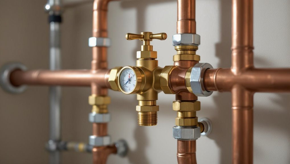
Choosing an appropriate TMV requires consideration of valve type and designated application—straightforward thermostatic cartridges suit single outlets, while larger modular or composite units serve showers, baths, or communal systems.
Correct sizing depends on expected flow rates, available supply pressures and temperatures to guarantee stable mixed-water delivery.
Material compatibility, relevant certifications (WRAS, ASSE, NHS/BS EN) and features such as scald protection, serviceability and anti-tamper options should be matched to the installation location.
Types of thermostatic mixing valves and typical applications
A thermostatic mixing valve (TMV) comes in several designs—such as single- or double-check, diverter, and remote-sensing models—each optimized for specific installations and safety requirements.
Selection depends on application: residential basins prefer compact single-check units; healthcare and care homes require approved double-check or fail-safe models; commercial showers often use remote-sensing or diverter TMVs.
Guidance on how to fit a thermostatic mixing valve follows system choice.
Sizing the TMV: flow rate, pressure, and temperature considerations
With the correct TMV type selected for the application, attention shifts to sizing so the valve delivers the required mixed temperature and flow under real operating conditions.
Calculate peak and typical flow rates, verify inlet hot and cold temperatures, and confirm minimum and maximum supply pressures.
Include pressure differential, flow coefficient (Cv or Kvs), and safety margins to guarantee stable temperature control and adequate delivery.
Materials, certifications, and standards to look for (WRAS, ASSE, NHS/BS EN)
Because a thermostatic mixing valve is both a safety device and a fluid control component, material composition and recognized certifications are essential to guarantee performance, longevity, and regulatory compliance.
Choose dezincification-resistant brass or stainless steel bodies, EPDM or suitable elastomers for seals.
Verify WRAS (UK), ASSE/ANSI (US), and BS EN/NHS approvals where applicable.
Look for corrosion, scale and lead-free compliance documentation.
Matching valve features to installation location (bathroom, shower, communal hot water)
After verifying materials and certifications, selection should pivot to the specific installation environment: bathrooms, showers, and communal hot-water systems impose different flow, temperature stability, and safety requirements.
Bathrooms require compact TMVs with anti-scald and easy service access.
Showers demand higher flow and rapid response to pressure changes.
Communal systems need robust, lockable, maintenance-friendly units with compliance to institutional standards and thermostatic accuracy.
Tools, Materials, and Safety Precautions Needed Before Starting
Before beginning work on a thermostatic mixing valve, a concise checklist of required tools and consumables should be prepared to guarantee the job proceeds without interruption.
Appropriate personal protective equipment and adherence to safe working practices protect installers from scalds, chemical exposure and mechanical injury.
The hot water system must be isolated, depressurised and drained according to standard procedures before any fittings are removed or adjusted.
Required tools and consumables checklist
A concise checklist of tools, materials, and safety gear guarantees efficient, safe installation of a thermostatic mixing valve.
Required items include accurate measuring, proper fittings, and consumables for reliable joints.
- Adjustable wrench, pipe cutter, and hex keys
- PTFE tape, flux, solder or compression fittings
- Isolation valves and compatible connectors
- Replacement thermostatic mixing valve and sealing washers
Personal protective equipment and safe working practices
With the checklist complete and materials staged, attention turns to personal protective equipment and safe working practices to prevent injury and protect the installation.
Gloves, eye protection, and steel-toe footwear are mandatory; hearing protection and respiratory masks added when soldering or cutting.
Use insulated tools, proper ladders, and secure work area lighting.
Follow lockout tags, minimize trip hazards, and maintain clear communication among workers.
Isolate, depressurise and drain procedures for hot water systems
Isolate the hot water system at its supply and return shut-off valves. Confirm the boiler or primary heat source is electrically and fuel-isolated using lockout-tagout.
Open a high-point vent to break any vacuum; then drain the relevant section into an appropriate container or drain and verify pressure has dropped to ambient using a gauge before cutting or disconnecting fittings.
Wear gloves, eye protection and hearing protection. Use compatible hoses, buckets, pressure gauge, spanners and a pan.
Pre-Installation Assessment of Existing Plumbing
Before fitting a thermostatic mixing valve, the existing plumbing must be assessed, including the hot water source, boiler or cylinder, and any expansion arrangements.
Operating pressures and temperatures should be measured to confirm compatibility and correctly set the valve.
Placement options (point-of-use versus system-level) and any required backflow or check valves must be identified to guarantee safe, code-compliant installation.
Inspecting hot water source, boiler, cylinder, and expansion arrangements
When evaluating the existing plumbing, the fitter should verify the type and capacity of the hot water source—boiler, unvented cylinder, or thermal store—and confirm that output temperatures and flow rates match the thermostatic mixing valve’s requirements.
They should inspect expansion vessels, pressure relief valves, and expansion pipework for correct sizing, condition, and isolation.
Note compatibility with system controls and record any necessary repairs or upgrades.
Measuring operating pressures and temperatures
Measure and record the system’s static and dynamic pressures and the actual hot and cold water temperatures at points representative of the TMV connection to guarantee the valve will operate within its rated range.
Use calibrated gauges and thermometers, note pressure fluctuations under typical demand, and log minimum and maximum values.
Compare readings to TMV specifications and local code limits to confirm compatibility before proceeding.
Identifying placement options: point-of-use vs. system-level installation
Several factors determine whether a thermostatic mixing valve should be installed at the point of use or at the system level: fixture types and locations, flow rates and simultaneous demand, available space and service access, and existing plumbing layout.
Decision criteria include proximity to high-risk fixtures, frequency of temperature adjustment, ease of maintenance, and whether centralized control simplifies balancing and reduces multiple valves versus individual protection at each fixture.
Evaluating backflow and check valve requirements
A preliminary assessment of existing backflow prevention and check valve arrangements is essential before installing a thermostatic mixing valve to guarantee potable water safety and code compliance.
Inspect for dual checks, reduced pressure zones, and directionality. Verify condition, test records, and compatibility with TPMV location.
Determine if additional backflow assemblies, isolation valves, or double-checks are required to prevent cross-connection and maintain system integrity.
Step-by-Step Installation Guide
The installation section outlines the practical sequence: marking positions, preparing and cutting pipework, and getting fittings ready for soldering or compression.
It then covers fitting the valve body with correct hot, cold and mixed port orientation, and adding isolation and check valves.
Finally, it addresses recommissioning steps including refilling, repressurising and flushing the system.
Marking position and preparing pipework
Begin by identifying the valve’s ideal mounting location relative to hot and cold supplies, the outlet to the mixed-water fixture, and any surrounding access restrictions; this guarantees pipe runs remain short, straight, and serviceable.
Next, mark inlet, outlet and drain positions on pipework and support points.
Verify clearances for isolating valves and test access.
Record measurements and annotate drawings for installer reference.
Cutting, deburring, and preparing connections for soldering or compression
With positions marked and clearances verified, attention shifts to cutting, deburring, and readying pipe ends for either soldered or compression fittings.
Use a proper pipe cutter for clean, square cuts. Remove burrs and filings with a deburring tool and file.
Clean surfaces with emery cloth or flux as required. For compression, inspect olives and verify correct insertion depth before assembly.
Installing the thermostatic mixing valve body (hot, cold, mixed ports orientation)
One careful placement sets the foundation: position the thermostatic mixing valve body so its ports align with the labeled hot, cold, and mixed supply lines, ensuring the orientation matches the valve’s flow markings and the planned plumbing layout.
Confirm inlet directions, maintain access for future servicing, verify clearances for temperature control and sensors, and temporarily support the valve to prevent strain before final connections are made.
Securing isolation valves and check valves around the TMV
After the valve body is aligned and temporarily supported, the installer moves on to fitting isolation and check valves to protect and service the TMV.
Isolation valves are fitted on hot, cold and mixed outlets for maintenance access; check valves prevent backflow between supplies.
All fittings are tightened to manufacturer torque, oriented for access, supported to avoid strain, and leak-tested before final enclosure.
Re-commissioning: refilling, repressurising and flushing the system
Begin refilling the system by isolating the TMV and opening the nearest inlet isolation valves to allow controlled flow into the network.
Repressurise to design pressure, vent air at high points and at thermostatic valve drains.
Flush until discharge is clear and free of debris.
Close drains, check for leaks, confirm isolation valves operate, and restore normal supply to complete re-commissioning.
Initial temperature set and adjustment procedure
Set the TMV to the preliminary temperature using the manufacturer’s adjustment mechanism, confirming inlet supplies are stable and at design pressures.
Allow the valve to stabilise, then measure mixed outlet temperature at representative outlets.
Make incremental adjustments until target temperature is achieved within tolerance.
Verify response to flow changes and pressure variations.
Record final setpoint and temperature readings for commissioning documentation.
Locking the adjustment and labeling the valve
Secure the adjustment to prevent unintended changes and apply clear identification for future maintenance and compliance.
The installer tightens the locking mechanism or fits the tamper-proof cap per manufacturer instructions, then verifies temperature.
Next, a durable label stating set temperature, date, installer, and commissioning details is affixed nearby.
Records are updated in maintenance logs and handover documentation to guarantee traceability and regulatory compliance.
Commissioning, Testing and Verification
Commissioning verifies that the valve delivers safe, stable temperatures under expected operating conditions using calibrated temperature measurement methods and defined acceptance criteria.
Tests should include pressure and temperature differential checks plus simulated cold- and hot-water failure scenarios to confirm fail-safe response.
All measurements, test results and settings must be recorded and documented to complete the commissioning paperwork.
Temperature measurement methods and acceptance criteria
Begin by identifying precise measurement locations and instruments to guarantee reliable verification of mixed water temperatures throughout the system.
Use calibrated digital thermometers or thermocouples, measuring at outlet points, distal fixtures, and recirculation loops after steady state.
Acceptance criteria: mixed water within specified setpoint ±2°C, no cold spots, and consistent readings over repeated measurements.
Record results and remediate deviations.
Pressure and temperature differential testing
With verified mixed water temperatures established, the next step is to evaluate pressure and temperature differentials across the TMV assembly and associated piping to confirm proper hydraulic balance and thermal performance.
Measure inlet and outlet pressures and temperature drop under flow.
Record static and dynamic conditions, compare against manufacturer limits, and identify excessive pressure loss, air pockets, or flow restrictions that could compromise regulation or require corrective actions.
Cold-water failure and hot-water failure simulation tests
When simulating cold-water and hot-water supply failures, the technician deliberately isolates one inlet at a time to verify the TMV’s fail-safe response and recovery behavior under realistic fault conditions.
Tests confirm outlet temperature moves to safe limits, shut‑off or diversion functions operate, and automatic rebalancing resumes when supply is restored.
Any deviations trigger adjustment, repair, or replacement before handover.
Recording commissioning data and completing paperwork
Documenting commissioning results and completing the required paperwork are essential steps to demonstrate that the thermostatic mixing valve has been installed, tested, and verified in accordance with specifications and regulations.
Records should include set temperatures, inlet pressures, test dates, installer details, adjustments, and evidence of cold/hot failure simulations.
Retain certificates, calibration logs, and user handover notes for compliance, maintenance planning, and future audits.
Maintenance, Servicing and Troubleshooting
A clear maintenance plan outlines recommended inspection intervals and routine tasks such as descaling, cleaning strainers and replacing cartridges to preserve valve performance.
The section then covers common faults and symptoms with stepwise troubleshooting procedures to identify causes quickly.
Guidance is provided on criteria for repair versus full replacement based on damage, age and cost-effectiveness.
Recommended maintenance schedule and service tasks
Because thermostatic mixing valves (TMVs) regulate water temperature for safety and performance, a clear maintenance schedule and defined service tasks are essential to guarantee reliable operation and compliance with standards.
Recommended routine:
- Quarterly visual inspection for leaks, corrosion and secure mounting
- Six‑monthly temperature checks and record keeping
- Annual functional test and calibration verification
- Replace worn seals or components as identified during service
How to descale, clean strainers and replace cartridges
Routine inspections and scheduled testing often reveal scale buildup, clogged strainers, and worn cartridges that impair thermostatic mixing valve performance; addressing these issues promptly preserves temperature stability and flow.
Isolate supplies, depressurize, remove strainers, and flush debris. Descale components with manufacturer-approved solution, rinse thoroughly, and inspect seals.
Replace cartridges per instructions, lubricate O-rings with approved grease, reassemble, pressure-test, and record service details.
Common faults, symptoms and stepwise troubleshooting
Several predictable faults affect thermostatic mixing valves, each producing distinct symptoms that guide targeted troubleshooting.
Temperature drift, no hot or cold flow, fluctuating output, leaking bodies, and noisy operation are common.
Inspect strainers, check supply pressures, verify thermostatic element movement, test cartridge seating, and replace seals.
Progress logically: isolate, observe, measure, clean, adjust, retest, record outcomes, and resume service.
When to repair vs. when to replace
After isolating, observing and testing a thermostatic mixing valve to identify faults such as temperature drift, poor flow or leaks, the next decision is whether to repair components or replace the entire valve.
Repair is suitable for isolated, inexpensive parts and when certification isn’t affected.
Replace when corrosion, multiple failures, obsolete parts, safety non‑compliance or warranty concerns exist, ensuring regulatory and performance integrity.
Compliance, Regulations and Documentation
Compliance with regional building regulations and plumbing codes is essential when fitting a thermostatic mixing valve, as specific requirements vary by jurisdiction.
Clear signage, permanent labeling and accurate installation records are typically required to demonstrate conformity and support future maintenance.
Responsibilities for meeting these obligations rest with installers, while homeowners and building managers must retain documentation and guarantee ongoing compliance.
Relevant building regulations and plumbing codes by region
Building regulations and plumbing codes governing thermostatic mixing valve (TMV) selection, installation, and testing vary by region and must be consulted before work begins; these rules define acceptable valve types, temperature limits, commissioning procedures, maintenance schedules, and documentation required for inspections and certification.
Regional examples include UK’s BS EN 1111/BS 8558, US plumbing codes and state amendments, and local health or hospital-specific standards; always verify jurisdictional requirements.
Required signage, labeling and installation records for compliance
Clear, durable signage and accurate installation records are essential components of thermostatic mixing valve (TMV) compliance, providing evidence of correct setup, safe operation, and facilitating future maintenance and inspections.
Signage must indicate set temperature, model, serial number and commissioning date. Labels on valve and adjacent piping clarify hot/cold outlets.
Installation paperwork should include test results, installer details, calibration settings and scheduled inspection dates.
Responsibilities of installers, homeowners and building managers
Installers, homeowners and building managers each hold distinct, legally and operationally important duties to confirm thermostatic mixing valves function safely and remain compliant.
Installers must follow standards, document settings, and provide certificates.
Homeowners should maintain records, report faults, and allow inspections.
Building managers confirm routine testing, staff training, access to manuals, and retention of compliance documentation for audits and liability mitigation.
Safety Considerations and Risk Mitigation
Beyond fitting the TMV, additional scald prevention measures—such as flow restrictors, pressure-balancing fittings, and user education—should be considered to protect vulnerable users.
Attention must be paid to Legionella control and overall hot-water temperature management, balancing microbiological risk with scald risk through system-wide strategies.
Finally, electrical and system isolation hazards during installation and maintenance require clear lockout procedures and safe working practices to prevent injury.
Scald prevention strategies beyond the TMV
Several supplementary measures reduce scald risk even when a thermostatic mixing valve (TMV) is properly fitted.
Regular maintenance, prompt repair of leaking or faulty taps, and installation of anti-scald fittings at outlets provide layered protection.
Flow restrictors and pre-set temperature controls limit extremes.
Clear labeling, user education, and routine checks guarantee vulnerable occupants are safeguarded and residual risks remain minimal.
Legionella control implications and hot-water temperature management
When managing hot-water systems with thermostatic mixing valves, balancing scald prevention against Legionella control requires careful temperature strategy and system design.
Facilities should store water at temperatures that limit Legionella (typically ≥60°C) while using TMVs or point-of-use controls to reduce delivered temperatures.
Routine flushing, temperature monitoring, risk assessments, and maintenance of insulation and circulation help minimise bacterial growth without compromising user safety.
Electrical and system isolation hazards
Although thermostatic mixing valve (TMV) work is primarily mechanical and hydraulic, electrical and system isolation hazards present significant risks during installation, commissioning, inspection, and maintenance.
Electric actuators, control panels and nearby circuits must be de-energised and locked off.
Isolate water supplies, depressurise systems and verify zero energy.
Use qualified electricians for electrical tasks, follow permit-to-work procedures and document isolation and restoration steps.
Cost Estimates, Timeframe and When to Hire a Professional
Typical material and labour costs for fitting a thermostatic mixing valve range from modest DIY expenses for a single valve to several hundred pounds/dollars for system-wide replacements with professional labour.
A single-point installation often takes an experienced person 1–2 hours, while whole-house or system upgrades can require a day or more including testing.
Hiring a certified plumber is recommended when existing plumbing is complex, access is restricted, there are mains-pressure systems or safety regulations apply, or if compliance documentation and warranty protection are needed.
Typical material and labour cost ranges
A straightforward estimate for fitting a thermostatic mixing valve ranges broadly depending on valve quality, installation complexity, and local labour rates. Typical material costs: basic valve £40–£120, premium £150–£400. Labour commonly £80–£300. Contingencies may raise totals; professional quotes recommended.
| Item | Emotional cue |
|---|---|
| Basic valve | Relief |
| Premium valve | Confidence |
| Labour | Assurance |
| Contingency | Caution |
Average installation time by scenario (single-point vs. system-wide)
Efficiency often determines whether a thermostatic mixing valve install is a quick workshop task or a multi-day project.
Single-point installs (sink or shower) typically take 1–3 hours including shutdowns and testing.
System-wide replacements or new manifold integration require 6–16 hours across one to two days, accounting for isolation, flushing, balancing and commissioning.
Complexity and access drive time.
Signs that the job should be done by a certified plumber
When should a certified plumber be called in? Complex systems, unclear piping, or unknown materials require professional assessment.
Signs include mixing valve replacement on multi-zone systems, persistent temperature fluctuation after DIY attempts, building code obligations, inaccessible shutoffs, or warranty voiding if unauthorized work occurs.
If cost estimates are significant or timeframes tight, hiring a certified plumber guarantees compliance, safety, and reliable performance.
Practical Installation Scenarios and Examples
The section presents concise, practical examples covering three common situations: a step-condensed checklist for installing a TMV on a domestic shower, installation at a hot-water cylinder to protect the whole house, and methods for retrofitting a TMV into tight or constrained pipe runs.
Each example highlights necessary components, key measurements, and critical safety checks. Readers are guided toward clear, actionable steps and common pitfalls to avoid.
Installing a TMV for a domestic shower (step-condensed checklist)
Begin by verifying system requirements and isolating the water supply: confirm inlet temperatures and pressures meet the TMV’s specifications, shut off hot and cold supplies, and drain the lines to prevent accidental discharge during installation.
Then follow a concise checklist:
- Mount TMV near shower outlet, accessible for maintenance
- Connect hot/cold inlets with correct orientation and seals
- Fit outlet to shower feed and test for correct mixed temperature
- Secure insulation and label valves for future service
Installing a TMV at a hot-water cylinder for whole-house protection
After completing a point-of-use TMV installation at a shower, attention shifts to protecting the entire distribution system by fitting a thermostatic mixing valve at the hot-water cylinder.
Installation requires isolating cylinder outlet, fitting TMV on hot supply with accessible service space, installing check valves and expansion provisions, setting factory temperature limits, and commissioning with temperature and flow checks to guarantee safe, compliant whole-house control.
Retrofitting a TMV in tight or constrained pipe runs
When space is limited, retrofitting a thermostatic mixing valve (TMV) demands careful planning to reconcile existing pipe geometry with the valve’s service clearances and flow requirements.
Assess access, measure straight-run needs, and choose compact or angled TMV models.
Use short remnant pipe sections, elbow adapters, and isolation fittings for maintenance.
Pressure and temperature balancing, plus compliant backflow and drain arrangements, remain mandatory.
Quick Reference Checklists
A set of concise checklists helps guarantee consistent outcomes when fitting a thermostatic mixing valve.
These should cover pre-installation checks (site conditions, incoming pressures, and component compatibility), commissioning steps (temperature settings, safety cut-ins, and leak tests), and annual service tasks (calibration, wear inspection, and sediment clearing).
Presenting them as quick-reference lists reduces the risk of missed steps and supports compliant maintenance.
Pre-installation checklist
One concise checklist itemizes site, system, and safety requirements to confirm readiness before installing a thermostatic mixing valve.
It guarantees correct components, clear access, and hazard controls.
Essential pre-installation checks include:
- Verify valve model, pressure and temperature ratings
- Confirm pipe sizes, fittings and isolation valves
- Ascertain adequate clearance and mounting support
- Check cold and hot supply stability and strainers are fitted
Commissioning checklist
With pre-installation items verified, attention shifts to commissioning to confirm the thermostatic mixing valve operates safely and to specification.
The technician follows a concise checklist to validate performance, stability, and compliance before handover:
- Verify supply pressures, flow rates, and correct orientation
- Set and lock outlet temperature
- Conduct cold and hot failure tests
- Record readings, tags, and commissioning certificate
Annual service checklist
Annual servicing confirms continued safe, accurate operation of the thermostatic mixing valve and identifies wear or drift before failures occur.
A qualified technician should perform the following checks annually to maintain compliance and safety:
- Inspect valve body, connections and check for leaks or corrosion
- Verify temperature accuracy and adjust setpoint if needed
- Test shut‑off and non‑return devices
- Clean strainers and replace worn seals or cartridges as required
Conclusion
To summarize, installing a thermostatic mixing valve protects users from scalding while meeting regulatory standards. Even a non‑professional might worry the process looks complex; a simple annotated diagram—showing cold and hot inlets, mixed outlet, isolation valves and bypass—clarifies connections and flow direction. With correct valve selection, basic tools, pressure checks and a thermometer verification, the task becomes manageable; otherwise, engaging a qualified plumber guarantees safety and compliance.