
How to Measure G I Fittings Accurately: Step-by-Step Guide for DIY and Pros
To measure G I fittings accurately, start by identifying the fitting type and thread standard. Gather the necessary tools: calipers, a thread gauge, and ensure you have a clean workspace. Measure the male outer diameter (OD) and female inner diameter (ID), verify the thread pitch and form, and compare your measurements to NPT, BSP, or metric charts. Check for any corrosion or coatings that may affect your readings and document your measurements for selecting compatible replacements. Before final installation, perform a dry assembly and low-pressure testing to ensure a proper fit. Follow these steps for precise measurements and successful results.
How to Choose the Right G I Fitting for Your Project
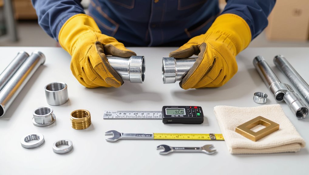
Choosing the right G I fitting begins with identifying common types—elbows, tees, couplings, and adapters—and their typical uses in plumbing, gas, and HVAC runs.
Material choice (galvanized iron, brass, stainless steel) should match corrosion resistance and pressure requirements.
Verify thread standards and sizes (NPT, BSP, metric) and guarantee fittings are compatible with the pipe material and the specific application.
Common types of G I fittings and where they’re used
A clear understanding of common G I (galvanized iron) fittings—elbows, tees, couplings, unions, reducers, and caps—helps determine the right component for each plumbing or mechanical connection.
Each fitting’s shape, thread type, and pressure rating indicate typical uses such as changing direction (elbows), branching lines (tees), joining pipes (couplings/unions), adapting diameters (reducers), or terminating runs (caps).
Guidance on how to measure g i fittings guarantees correct sizing and fit.
Material considerations: galvanized iron, brass, stainless steel
Material selection shapes performance, longevity, and cost when fitting galvanized iron (GI) systems; galvanized iron, brass, and stainless steel each offer distinct trade-offs in corrosion resistance, strength, and machinability.
Galvanized iron is economical and strong but prone to surface corrosion over time.
Brass resists dezincification and machines well for decorative or potable uses.
Stainless steel provides superior corrosion resistance and longevity, at higher cost and harder machining.
Thread standards and sizes to know (NPT, BSP, Metric)
Because compatibility hinges on thread form and pitch, understanding NPT, BSP, and Metric standards is essential when specifying GI fittings.
NPT is tapered and common in North America; BSP includes BSPT (tapered) and BSPP (parallel) used internationally.
Metric threads follow ISO pitch/diameter conventions.
Measure diameter and pitch with calipers and thread gauges, and reference standard charts to confirm correct size.
Matching fittings to pipe type and application (water, gas, HVAC)
Having confirmed thread form and size, selection shifts to matching GI fittings with the service and pipe type to guarantee pressure rating, corrosion resistance, and sealing method align with the application.
Materials and coatings differ: galvanized steel suits water, stainless or brass resists corrosion for potable lines, and specialized fittings with gas-approved seals and pressure ratings are required for gas.
HVAC demands vibration-resistant, temperature-rated options.
Tools and Preparation Needed Before Measuring
Before measuring G I fittings, a checklist of essential tools—tape measure, calipers, thread gauge, marker and shop rag—should be assembled.
Appropriate safety gear and a clean, well-lit workspace must be arranged to prevent injury and guarantee accurate readings.
Existing fittings and any factory markings or stamped sizes should be identified and noted prior to taking measurements.
Essential tools list
Accurate measurement of G I fittings requires a small set of reliable tools and a clear workspace: a calibrated tape measure or vernier calipers for diameters and lengths, a straight edge or ruler for face-to-face dimensions, a set of thread gauges for identifying thread pitch and form, and a flashlight for inspecting seating surfaces and threads.
- Vernier calipers
- Tape measure
- Thread gauges
- Straight edge/ruler
- Flashlight
Safety gear and workspace setup
A small selection of personal protective equipment and an organized, well-lit workspace are essential before measuring G I fittings.
Safety goggles, gloves, and steel-toe footwear protect against sharp edges and dropped parts.
Guarantee a sturdy bench, clear surface, and task lighting.
Keep measuring tools calibrated and within reach.
Secure fittings to prevent movement and dispose of debris promptly to maintain a safe area.
How to identify existing fittings and markings
With safety gear in place and the workspace prepared, attention shifts to identifying the existing G I fittings and any markings that will guide measurement.
Inspect fittings for stamped sizes, thread types, manufacturers’ logos, and paint or tag codes. Note orientation, damaged threads, or compression rings.
Photograph details and record markings before disassembly to guarantee accurate measurement and correct replacement.
Quick Overview: How to Measure a G I Fitting Accurately
For experienced DIYers, a quick accurate measurement of a G I fitting means confirming thread type, measuring major diameter, and counting threads per inch with calipers or a thread gauge.
The process begins with cleaning the fitting and visually identifying whether it is tapered or parallel.
A single clear measurement round typically yields the information needed to select a matching connector.
Single-sentence summary for experienced DIYers
Measure the thread OD of the male G fitting or the internal thread diameter of the female fitting with vernier calipers. Confirm thread pitch with a gauge or ruler, and match the dimensions to the G (BSPP) standard to select the correct connector.
An experienced DIYer then verifies seal type (parallel), checks mating thread engagement, and confirms pressure and material compatibility before final installation.
Step-by-Step Measurement Process for Threaded G I Fittings
The procedure begins with measuring the outside diameter (OD) of male threads and the inside diameter (ID) of female threads to establish basic size.
Next, thread pitch or threads per inch (TPI) are counted and the thread form and included angle are identified to match mating parts.
Finally, the effective pipe size is confirmed against the fitting size to guarantee proper fit and function.
Step 1 Measure outside diameter (OD) of male threads
Begin by identifying the male threaded end and placing calipers across the outermost points of the threads to record the outside diameter (OD) in millimeters or inches.
Verify calipers are perpendicular to the axis, take multiple readings at different rotations to account for wear or burrs, and note the largest consistent measurement.
Clean threads beforehand for accuracy.
Step 2 Measure inside diameter (ID) of female threads
Next, confirm the female threaded end is free of debris and place calipers inside the bore to span the innermost points of opposing threads, recording the inside diameter (ID) in millimeters or inches.
Verify caliper jaws contact the thread roots, not peaks. Take multiple measurements at different depths to detect taper or irregularities, then average readings and note measurement units.
Step 3 Measure thread pitch and count (TPI or mm)
After confirming the inside diameter, attention shifts to measuring thread pitch and count to determine whether threads are specified in threads per inch (TPI) or millimeters per thread.
Use a thread gauge or calipers to measure distance between adjacent crests; for TPI, count threads over one inch or scale fractionally.
Record pitch precisely and note handedness; this guarantees correct matching and replacement.
Step 4 Determine thread form and angle
Examine the thread profile to identify its form and measure the flank angle, since these characteristics determine compatibility with mating parts and sealing performance.
Inspect root and crest shapes to distinguish parallel, tapered, buttress, or V-threads. Use optical comparator or protractor on a clean cut face for angle verification.
Record type and angle to guarantee correct replacement, sealing method, and tooling selections.
Step 5 Confirm effective pipe size vs. fitting size
A final verification compares the fitting’s thread dimensions to the effective pipe size (EPS) to verify proper flow capacity and pressure rating.
The inspector matches major and minor diameters, pitch, and engagement length against EPS charts. Any mismatch can reduce flow or compromise sealing.
Confirming compatibility prevents pressure loss, turbulence, and safety hazards before final selection or installation.
Step 6 Record measurements and translate to standard size
With the fitting’s thread and EPS confirmed, the inspector logs the measured major and minor diameters, pitch, and engagement length in a standardized record form.
Recorded values are compared to manufacturer charts or ANSI/ISO tables to determine nominal pipe or fitting size.
Notes include tolerance deviations, thread class, and any damage.
Final entry assigns the standard designation for procurement and verification.
How to Measure Compression and Flare Style G I Fittings
Measurement of compression and flare style G I fittings begins with recording the nut size and ferrule dimensions to guarantee proper seating.
The tube outside diameter and wall thickness are then verified to match the fitting’s specifications.
Finally, these measurements are cross-referenced with manufacturer part numbers to determine the correct replacement.
Measuring nut size and ferrule dimensions
Several simple steps clarify how to measure nut size and ferrule dimensions on compression and flare G I fittings.
The observer measures across flats with calipers for nut width, notes thread type and pitch, and records nut thickness.
For ferrules, measure outer diameter, overall length, and internal bore where accessible.
Document measurements and compare to manufacturer charts for correct replacement or matching.
Checking tube OD and wall thickness
After recording nut and ferrule dimensions, attention shifts to the tubing itself: outer diameter (OD) and wall thickness determine fit, seal integrity, and pressure rating for compression and flare G I fittings.
Measure OD with a caliper at multiple points; average readings.
Measure wall thickness with a micrometer or tube gauge, or calculate from OD minus internal diameter if ID is known.
Record tolerances.
Determining correct replacement part numbers
Which part number fits a given compression or flare G I assembly depends on several precise attributes: thread type and size, nut and ferrule dimensions, tubing OD and wall thickness, material, and any special coatings or pressure ratings.
Match measurements to manufacturer catalogs, cross-reference OEM codes, and verify compatibility charts. Confirm torque and sealing method.
Record part numbers, substitutions, and batch details for future maintenance.
Using Gauges, Templates, and Digital Tools
A thread pitch gauge should be matched to the thread profile and seated flat to confirm thread count without damaging the fitting.
Calipers and micrometers provide precise diameter and length readings when used perpendicular to the axis and zeroed before each measurement.
Smartphone apps and digital readers can record, convert, and compare measurements to templates, speeding identification and reducing manual errors.
How to use a thread pitch gauge correctly
Several compact, purpose-made blades are required to use a thread pitch gauge correctly; each blade corresponds to a specific threads-per-inch (TPI) or millimeters-per-thread standard and must be matched precisely to the workpiece.
Select the matching blade, lay it into the thread root without forcing, verify full contact along several teeth, and confirm by checking multiple positions around the circumference before recording the pitch.
Using calipers and micrometers for precision
Precision measuring tools such as calipers and micrometers provide repeatable, quantifiable measurements essential for fitting G I threads within tolerance limits.
Operators should use vernier or digital calipers for outside, inside, and depth dimensions; micrometers for precise outer diameters.
Guarantee zeroing, clean contact faces, consistent measuring force, and temperature-stable parts.
Record readings, compare to specification, and inspect multiple points for runout.
Apps and digital readers that assist measurement
Leverage smartphone apps and dedicated digital readers to streamline G I fitting measurements and reduce human error.
These tools capture thread profiles, convert units, and log dimensions. Bluetooth digital calipers, template-matching apps, and laser distance readers speed repeatable checks and record timestamps.
Verify calibration, cross-check with physical gauges, and export data for traceability. They improve accuracy and workflow efficiency when used correctly.
Converting Measurements to Standard Fitting Sizes
The article then outlines how measured values—such as outer diameter, inner diameter, and thread pitch—are translated into standard nominal sizes using common conversion charts for NPT, BSP, and metric systems.
Practical examples show converting OD/ID/pitch readings to the nearest nominal fitting size and highlight when measurements are ambiguous.
Manufacturer specifications are recommended when charts and measurements do not provide a definitive match.
Common conversion charts for NPT, BSP, and metric
When converting measured diameters and thread pitches into standard fitting sizes, technicians rely on compact conversion charts that map NPT, BSP, and metric designations to actual dimensions. Charts list nominal size, thread pitch, and major/minor diameters for quick reference. Common tables cover 1/8″–1″ NPT, 1/8″–1″ BSP, and M6–M30 metric sizes.
| Nominal | Pitch | Major Ø |
|---|---|---|
| 1/8 NPT | 27 | 9.7 mm |
| 1/4 BSP | 19 | 13.2 mm |
| M10 | 1.5 | 10.0 mm |
Examples: converting OD/ID/pitch to nominal fitting size
Several concise examples illustrate how measured outside diameter (OD), inside diameter (ID), and thread pitch are translated into nominal fitting sizes.
For instance, a 0.840″ OD with 14 TPI commonly maps to 1/2″ NPT.
A 20.0 mm OD with 1.5 mm pitch often corresponds to M20 metric.
A 0.545″ ID with 14 TPI matches 3/8″ BSP.
These conversions guide selection and verification.
When to consult manufacturer specs
Although field measurements often narrow possibilities, manufacturers’ specifications remain essential for final confirmation. They provide exact thread form, tolerances, sealing face details, and material or coating information that simple OD/ID/pitch checks cannot reveal.
Consult specs when fittings are used under pressure, in corrosive environments, have mixed standards, require traceability, or when repairs must match original performance to guarantee safety and compatibility.
Common Measurement Challenges and How to Overcome Them
Common measurement obstacles include damaged or corroded threads, restricted access in tight or installed locations, and the need to distinguish similar standards such as NPT and BSP.
Each issue requires specific techniques—thread restoration or gauging for damaged threads, specialized tools or remote measuring methods for confined spaces, and pitch/angle checks or reference gauges for standard identification.
Addressing these challenges systematically improves accuracy and reduces fitting mismatches.
Dealing with damaged or corroded threads
Inspecting damaged or corroded threads requires careful attention, since rust, nicks, or flattened crests can obscure pitch and diameter measurements.
Clean residue with a wire brush and penetrating solvent, then use a thread gauge on multiple crests to confirm pitch. Measure core and major diameters away from damaged zones.
When uncertainty persists, compare with a sacrificial sample or consult a replacement chart.
Working in tight or installed locations
After addressing thread damage, attention turns to the added difficulty of measuring fittings that remain installed or sit in confined spaces.
Practitioners use compact calipers, flexible tape, and mirror scopes to capture outside diameters and lengths.
When access is impossible, notes and clear photos guide removal and replacement.
Patience, steady hands, and proper lighting reduce errors and prevent further damage during measurement.
Distinguishing similar thread standards (NPT vs BSP)
Because many fittings look alike to the eye, distinguishing NPT from BSP threads requires careful measurement and attention to profile: NPT is tapered with a 60° thread angle and measured by nominal pipe size, while BSP comes in parallel (BSPP) or tapered (BSPT) forms with a 55° thread angle and different pitch conventions.
Measure pitch, diameter, and taper; compare to reference gauges or charts to confirm standard.
Mistakes to Avoid When Measuring G I Fittings
The author warns against common measurement mistakes that compromise G I fitting accuracy.
These include relying on visual guesswork, mistaking pipe outside diameter for thread outside diameter, and overlooking how thread sealant or tape alters effective thread engagement.
Avoiding these errors preserves fit and prevents leaks.
Relying on visual guesswork
Relying on visual guesswork when measuring G I fittings often produces inaccurate dimensions and costly rework. Observers who estimate by eye miss thread pitch, taper, chamfers, and seating surfaces.
Measurements should use proper tools—calipers, thread gauges, and a straightedge—and follow documented procedures.
Visual assumptions also obscure wear or damage that alters fit, leading to leaks or assembly failure.
Confusing pipe OD with thread OD
A common measurement error follows from mistaking a pipe’s outside diameter (OD) for the thread OD of a G I fitting.
The pipe OD and thread OD differ because G threads reference nominal bore and crest/root geometry. Measuring the exposed thread crest with calipers or using a thread gauge yields correct identification.
Confusing the two leads to mismatched fittings, leaks, and wasted materials.
Ignoring thread sealant and tape effects
Although often overlooked, sealants and PTFE tape add measurable thickness to G I threads and can distort caliper and thread-gauge readings.
Inspect fittings and remove all tape or cured sealant before measuring. If removal is impossible, note the coating thickness and compensate in measurements.
Document whether readings reflect bare metal or coated threads to prevent mismatches when ordering or matching fittings.
Practical Examples and Walkthroughs
The article presents three concise, real-world walkthroughs to illustrate correct measurement techniques.
Example A covers replacing a garden hose spigot fitting with step-by-step measurements and common pitfalls.
Example B shows measuring a gas-line coupling for replacement.
Example C explains how to identify size from an unmarked old fitting.
Example A Replacing a garden hose spigot fitting
When replacing a garden hose spigot fitting, the installer first shuts off the water supply and drains the line to prevent leaks.
Next, the old spigot is removed, its connection type and thread size are inspected, and a matching G I F fitting is selected to guarantee a secure, leak-free replacement.
Threads are measured with calipers, tape direction noted, sealant or tape applied, and fit tested.
Example B Measuring a gas-line coupling for replacement
Measure the gas-line coupling with care, beginning by shutting off the gas and ventilating the area to eliminate ignition risk; then depressurize the line and confirm zero gas flow with a detector before touching fittings.
Use calipers to record outer diameter and thread pitch, note thread type (NPT/pipe), measure wall thickness if accessible, and photograph orientation.
Replace with equivalent rated coupling and retest for leaks.
Example C Identifying size from an unmarked old fitting
How can an unmarked, weathered fitting be identified quickly and accurately?
The technician cleans corrosion, measures outer and inner diameters with calipers, and notes thread pitch using a gauge or ruler.
Comparison to known G I size charts confirms nominal size.
If uncertain, test-fit with sacrificial adapters or consult historical schematics before replacing to guarantee correct compatibility and seal.
Buying, Testing, and Installing Replacement Fittings
Before purchasing replacement G I fittings, the reader should confirm dimensions, thread type, and clearance to verify a proper trial fit on a spare coupler or test assembly.
Recommended sealants, tapes, and specified installation torque must be matched to the fitting material and system pressure to prevent leaks and avoid damage.
If measurements are uncertain, threads are damaged, or the installation involves high pressure or critical systems, a professional installer should be engaged.
How to verify fit before final installation
Confirming a proper fit prior to final installation prevents leaks, damage, and wasted time.
The installer aligns threads, seats, and contact surfaces dry, checks thread engagement depth and alignment, and verifies clearances and rotation.
A temporary assembly under low pressure or with compressed air and soapy water reveals misfits.
Document measurements and any deviations before finalizing component selection and placement.
Recommended sealants, tapes, and installation torque
Selecting appropriate sealants, tapes, and installation torque is critical to guarantee leak-free, durable GIF fitting connections; choices should match materials, media, and operating conditions.
Use compatible thread sealants (PTFE tape for non-reactive fluids, anaerobic or pipe dope for metal threads), avoid overuse, and apply recommended torque values from manufacturers.
Verify seals under test pressure and re-torque per service intervals to prevent creep and leaks.
When to choose a professional installer
When should a professional installer be engaged for GIF replacement fittings depends on the complexity of the system, the consequences of failure, and the available in-house expertise.
High-pressure, hazardous-fluid, or regulated installations warrant certified professionals.
Complex geometries, concealed access, or tight tolerances also justify hire.
Limited tools, lack of testing equipment, or warranty requirements further tip the decision toward professional installation to guarantee safety and compliance.
Quick Reference Cheat Sheet
A compact checklist presents the fast measurement steps needed for accurate G I fitting identification.
It lists common sizes and simple ID tips to match fittings quickly.
Readers can use the sheet as a quick-reference during inspection, ordering, or installation.
Fast measurement checklist
Every essential dimension and tool is listed for quick on-site verification: thread size, pitch, male/female type, seat angle, outer diameter, and required wrench flats, plus calipers, pitch gauge, and thread gauge.
A concise checklist guides fast, repeatable checks before ordering or fitting.
- Confirm male/female and seat type
- Measure thread pitch
- Record outer diameter
- Note wrench flat size
- Verify tool availability
Common sizes and quick ID tips
Because standard G (BSP) and ISO fittings follow predictable series and markings, technicians can rapidly narrow candidates by a few key measurements and visual cues. Common sizes: 1/8″, 1/4″, 3/8″, 1/2″, 3/4″, 1″. Quick ID: thread pitch, OD, hex size, seal type.
| Size | OD (approx) | Tip |
|---|---|---|
| 1/8″ | 9.7mm | fine pitch |
| 1/4″ | 13.2mm | common on instruments |
| 1/2″ | 20.9mm | check hex flats |
Conclusion
In the end, the reader is left marveling at the high drama of plumbing precision: tiny threads and collars, each demanding reverence and a micrometer. Armed with tape, calipers and humility, one emerges victorious, or at least un-flooded. This manual has quietly promised competence to both weekend warriors and smug professionals, proving that measuring metal can be elevated to an art form—assuming no one confuses inches with millimetres during the final, catastrophic twist.
