How to Install a Thermocouple on a Gas Fireplace: Step-by-Step Safety Guide
Installing a thermocouple on a gas fireplace is crucial for safety, as it detects the pilot flame and shuts off gas if the flame extinguishes. To begin, turn off the gas and power to the fireplace. Gather the necessary tools: a wrench, pliers, multimeter, and a thermocouple of the appropriate length.
Next, remove the access panel and loosen the fittings to access the thermocouple. Carefully route and secure the probe in the pilot flame, then tighten all connections. After installation, test the millivolt output and pilot hold, and check for gas leaks. Follow the detailed step-by-step instructions for further tests, troubleshooting, and safety checks to ensure everything is functioning correctly.
Overview of Installing a Thermocouple on a Gas Fireplace
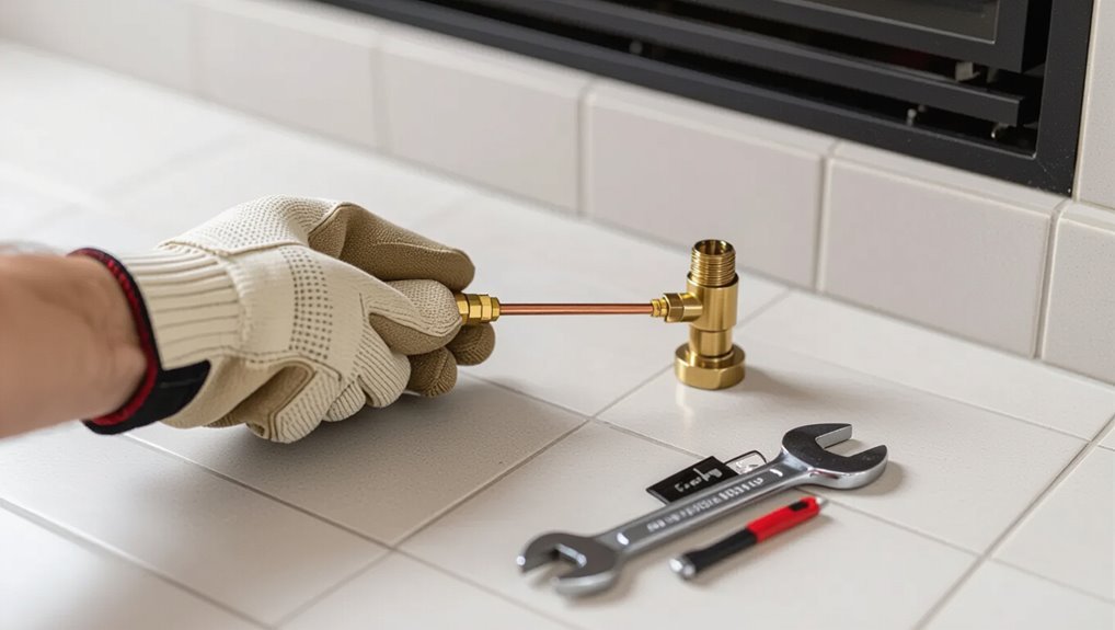
A thermocouple senses pilot flame presence and prevents gas flow if the flame goes out, making it a critical safety component for gas fireplaces.
Common signs that it needs replacement include a weak or extinguishing pilot light, intermittent shutdowns, or visible corrosion.
Basic mechanical skills and attention to safety are sufficient for many replacements, but gas line issues, uncertain diagnosis, or local code requirements warrant calling a qualified technician.
What a thermocouple does and why it matters for fireplace safety
Recognizes heat and prevents danger: the thermocouple is a small but essential safety sensor that detects whether the pilot light on a gas fireplace is burning and, if not, shuts off the gas supply. It guarantees safe operation and guides decisions about how to install a thermocouple on a gas fireplace.
| Function | Effect |
|---|---|
| Detect heat | Keeps gas closed |
| Fail-safe | Prevents leaks |
Signs you need to replace or install a thermocouple
When should a thermocouple be replaced or newly installed? Persistent pilot light outages, intermittent flame dropouts, or a pilot that won’t stay lit indicate thermocouple failure.
Visible corrosion, soot accumulation, or bent/damaged sensor tubing also signal replacement.
Recent repairs, component age beyond manufacturer recommendations, or inconsistent gas flow and safety shutoffs justify installing a new thermocouple to restore reliable flame sensing.
Required skills, warnings, and when to call a professional
Installers should possess basic mechanical aptitude, familiarity with gas appliance components, and comfort using hand tools and a multimeter to test continuity and millivoltage; otherwise, the task risks improper sensing or leaks.
They must follow gas shutoff, ventilation, and ignition safety. If unsure about gas fittings, corrosion, pilot assembly alignment, or local codes, contact a licensed HVAC or gas technician to prevent hazards and code violations.
Tools, Parts, and Materials Needed
The section lists compatible thermocouple types and common lengths or diameters suited to gas fireplaces.
It then provides a concise tools checklist—wrenches, screwdrivers, needle-nose pliers, and a multimeter—for safe removal and installation.
Finally, a parts checklist covers replacement nuts, fittings, and typical pilot assembly components to confirm on-hand inventory before starting.
Compatible thermocouple types and sizes for gas fireplaces
Choosing the correct thermocouple for a gas fireplace depends on type, length, and diameter to guarantee reliable flame sensing and safe operation.
Common types include Type K and Type J; most fireplaces use a copper-nickel (constantan) or nickel-chromium element with steel sheathing.
Typical diameters are 3/16″ or 1/8″, lengths 6″–24″. Match fittings and connector threads to the pilot assembly.
Tools checklist
Several essential tools and a few specific parts guarantee a smooth thermocouple installation on a gas fireplace.
The installer should prepare basic hand tools, safety equipment, and replacement components while avoiding pilot assembly specifics reserved for the next section.
- Adjustable wrench, needle-nose pliers, and socket set
- Multimeter for continuity and millivolt checks
- Safety glasses, gloves, and a flashlight
Parts checklist (nuts, fittings, pilot assembly components)
After gathering the listed tools, attention shifts to the specific parts required for a reliable thermocouple installation.
Essential components are verified for fit, condition, and compatibility before starting work.
- New thermocouple with correct length and connector
- Brass compression fitting, nuts, and ferrules sized to the pilot tube
- Pilot assembly parts: pilot hood, orifice, mounting bracket, and gasket
Preparatory Safety Steps Before Starting
Before beginning work on the thermocouple, the technician verifies gas and electrical supplies are shut off and confirms isolation at the appliance.
The area is ventilated and cleared of combustible materials or ignition sources to reduce fire risk.
The pilot assembly and surrounding components are then visually inspected for damage, leaks, or residue that could affect safe operation.
Shutting off gas and power and verifying isolation
Begin by locating and closing the gas shutoff valve feeding the fireplace, then switch off its electrical supply at the breaker or appliance switch to eliminate ignition and control power. Confirm zero gas flow and no power with a handheld meter or sniff test. Record isolation status and tag the breaker.
| Item | Action | Verification |
|---|---|---|
| Gas valve | Closed | Visual/manual |
| Breaker | Off | Tester/label |
| Appliance switch | Off | Indicator |
| Tags | Applied | Date/name |
| Tools | Meter/sniffer | Readings recorded |
Ventilation and fire hazard precautions
With gas and electrical isolation confirmed and documented, attention shifts to ventilation and fire-hazard precautions to secure a safe working environment.
The technician verifies adequate fresh air flow, opens nearby windows or vents, and uses exhaust fans if needed.
Flammable materials are removed, combustible surfaces shielded, and a fire extinguisher rated for gas fires is staged within reach before work begins.
Inspecting the pilot assembly and surrounding components
One careful visual inspection of the pilot assembly and adjacent components helps identify obvious defects or hazards before any hands-on work begins.
The inspector notes corrosion, loose fittings, soot, wire insulation damage, and gas smell.
Check pilot orifice, thermopile connections, mounting brackets, and nearby combustible debris.
Record faults, shut off gas, and arrange professional repair for anything beyond basic cleaning or tightening.
Step-by-Step Thermocouple Installation
The technician begins by removing access panels to reveal the pilot assembly and identifying the existing thermocouple.
After safely disconnecting the old unit, the technician compares the replacement to verify correct length, thread type, and probe orientation.
The new thermocouple is routed and positioned alongside the pilot flame, then secured to the pilot assembly and control valve following manufacturer torque and alignment recommendations.
Removing access panels and locating the pilot assembly
Begin by powering off the fireplace and ensuring the gas supply is shut to prevent any risk while working. Remove screws or clips from the access panel, set hardware aside, and gently lift the panel. Locate the burner and pilot assembly near the control valve; the pilot is small with a thermocouple nearby. Confirm clear access before proceeding.
| Panel Type | Fastener | Location |
|---|---|---|
| Front | Screws | Bottom |
| Side | Clips | Left |
| Rear | Screws | Right |
| Floor | Bolts | Center |
Disconnecting the old thermocouple safely
Power is confirmed off and the gas supply remains closed before any components are touched; this guarantees a safe environment for disconnecting the thermocouple.
The technician loosens the retaining nut at the pilot assembly, gently withdraws the probe from the pilot bracket, and detaches the lead from the gas valve.
Removed parts are set aside on a clean surface for inspection or replacement.
Comparing old and new thermocouples for fit and type
With the old thermocouple removed and laid out for inspection, the technician compares its length, probe diameter, thread size, and connector type to the replacement unit.
He verifies material compatibility, mounting orientation, and insulation condition.
Any mismatch in threads, connector polarity, or probe dimensions prompts selecting a correct aftermarket part or adapter.
Documenting part numbers guarantees future replacements match precisely.
Routing and positioning the new thermocouple
Carefully route the new thermocouple so its probe sits securely in the pilot flame while the sheath and wiring remain clear of moving parts and hot surfaces.
Guide the lead along existing clips or brackets, avoiding sharp bends and kinks. Maintain a gentle curve to prevent stress at connection points.
Confirm the probe tip alignment with flame center before final adjustments and reassembly.
Securing the thermocouple to the pilot assembly and control valve
After confirming the probe tip is centered in the pilot flame and the lead follows a gentle, secure path, the installer fastens the thermocouple to the pilot assembly and control valve.
They hand-tighten the compression nut at the valve, align mounting brackets or clips on the pilot housing, secure any retaining screws, and guarantee the thermocouple sits without strain or contact with moving parts before testing.
Reconnecting gas line fittings and tightening to specification
Reattach the gas line fittings by hand at first, ensuring threads engage cleanly and the thermocouple lead remains free of pinch points.
Once hand-tight, use the correct-size wrench to tighten each connection to the manufacturer’s specified torque, avoiding over‑tightening that can strip fittings or crush soft seals.
Verify alignment, inspect flare or compression joints for uniform contact, and back off if resistance or misalignment appears before final torque.
Restoring gas and power and initial lighting procedure
With the fittings secured and checked for proper alignment, attention shifts to restoring the gas and electrical supplies and performing the initial lighting.
The technician opens the main gas valve slowly, restores power at the breaker, then follows the manufacturer’s lighting procedure: purge air if required, ignite pilot, verify steady flame enveloping the thermocouple, observe for leaks and correct operation before final reassembly and monitoring.
Testing and Verifying Proper Operation
After installation, inspection focuses on flame shape and the thermocouple’s secure contact with the pilot flame.
A pilot-hold test and observation of the gas valve’s response verify that the system maintains ignition under normal conditions.
A basic multimeter check of the thermocouple’s millivolt output confirms electrical functionality and helps pinpoint faults.
Flame shape and thermocouple contact checks
Inspect the pilot flame and thermocouple connection to confirm reliable operation: the pilot flame should envelop the thermocouple tip with a steady, blue cone and minimal yellow tipping.
The thermocouple nut and mounting should be clean, tight, and free of corrosion or soot that can prevent proper heat transfer.
Verify proper alignment and firm contact; gently adjust positioning if flame impinges or misses the sensor.
Performing a pilot hold test and valve response
Begin the pilot hold test by lighting the pilot and holding the control knob in the “pilot” position for the recommended time (typically 20–30 seconds) to confirm the thermocouple heats sufficiently for the safety valve to remain open.
Observe valve behavior: if the main burner lights when the knob is released to “on,” the valve responds correctly.
If it shuts off or is delayed, inspect thermocouple alignment and connections or replace faulty components.
Using a multimeter to test millivolt output (basic procedure)
Use a digital multimeter set to the millivolt (mV) range to verify that the thermocouple is producing the proper voltage when heated by the pilot flame.
The technician follows a concise test procedure:
- Disconnect thermocouple from gas valve and connect multimeter leads to terminals.
- Heat tip with pilot flame until stable reading appears.
- Expect roughly 20–30 mV; lower indicates replacement or poor contact.
Common Problems During or After Installation and How to Fix Them
Common problems after installing a thermocouple include a pilot that won’t stay lit, a weak flame from incorrect thermocouple positioning, and gas leaks at fittings.
Technicians should check and realign the thermocouple tip for a strong blue flame, use a soap solution and tighten fittings in order from appliance to supply to locate and stop leaks, and verify millivolt output with a meter.
If millivolt readings are inconsistent or the control valve fails to respond, replacement of the control valve may be required.
Pilot not staying lit likely causes and fixes
Several issues can cause a pilot flame to extinguish shortly after lighting, and diagnosing them requires checking both mechanical and environmental factors.
- Dirty pilot orifice: clean or replace to restore steady gas flow.
- Faulty thermocouple or connection: test continuity and tighten or replace if cold.
- Drafts or ventilation problems: eliminate airflow, adjust vents, or seal gaps to stabilize the flame.
Weak flame or improper thermocouple positioning
Inspecting flame strength and thermocouple placement reveals two frequent issues after installation: a weak, sputtering flame that fails to envelop the thermocouple, and a thermocouple misaligned or seated too far from the pilot flame.
Remedies include cleaning pilot orifices, removing debris, adjusting air shutter or pilot screw for a steady blue flame, and repositioning the thermocouple tip about 1/4–1/2 inch into the flame.
Leaks at fittings detection and tightening sequence
Once flame strength and thermocouple placement are verified, attention should turn to the gas fittings, since leaks at joints are a frequent source of post-installation problems. Inspect with soapy water, watch for bubbles, tighten fittings sequentially from supply to appliance, then retest. If persistent, replace seals or connectors and pressure-test per code.
| Step | Action | Result |
|---|---|---|
| 1 | Inspect | Detect leak |
| 2 | Soapy test | Visual bubbles |
| 3 | Tighten supply→appliance | Reduce leak |
| 4 | Retest | Confirm seal |
Electrical/millivolt issues and when to replace the control valve
Troubleshoot electrical and millivolt systems promptly, since weak or intermittent signals often mimic gas problems and can prevent the thermocouple from allowing valve operation.
Check wiring continuity, ground integrity, and millivolt output with a multimeter. Replace batteries or rectifiers if present.
If millivolt output is within spec but the valve fails to hold/open, replace the control valve—faulty guts cause intermittent or unsafe operation.
Maintenance and Longevity Tips
Routine inspections and gentle cleaning keep a thermocouple functioning reliably and help prevent soot buildup.
Proper positioning, avoiding flame impingement, and using a soft brush or compressed air can extend component life.
Clear criteria for replacement—persistent failure to hold pilot, visible corrosion, or repeated cleaning without improvement—should guide when to replace rather than repair.
Regular inspection schedule and cleaning tips
A simple, consistent inspection schedule helps assure a thermocouple and its gas fireplace remain safe and reliable. Monthly visual checks, annual professional inspections, and gentle cleaning prevent buildup and guarantee proper flame contact. Replace damaged parts promptly. Follow manufacturer guidelines and shut off gas before work.
| Frequency | Task | Notes |
|---|---|---|
| Monthly | Visual check | Look for debris |
| Quarterly | Light clean | Use soft brush |
| Annually | Professional service | Safety inspection |
| As needed | Replace parts | Corrosion or wear |
How to extend thermocouple life and prevent soot accumulation
Following regular inspections and timely cleaning, attention shifts to practices that prolong thermocouple life and prevent soot buildup on a gas fireplace.
Use correct pilot flame adjustment to avoid incomplete combustion, maintain proper ventilation, and burn recommended fuels.
Inspect burner ports for blockages, clean gently with a soft brush, and schedule annual professional servicing.
Tighten connections and avoid corrosive cleaners to reduce wear.
When to replace rather than repair
When is repair no longer practical? The thermocouple shows repeated intermittent operation, visible corrosion, or fails safety checks despite cleaning.
If repair costs approach replacement price, threads or fittings are stripped, or modern safety standards aren’t met, replacement is advised.
A new thermocouple restores reliable pilot control, reduces fire risk, and guarantees compatibility with updated valves and appliance warranties.
Safety Checklist and Final Walkthrough Before Use
A final safety checklist and walkthrough confirm that the thermocouple installation is secure and the fireplace operates safely.
- Visual inspection items: fittings, heat shields, and visible wiring.
- Functional tests to perform: gas shutoff, pilot ignition, and thermocouple response.
- Documentation and parts records to keep: installation notes, replacement parts, and service dates.
Visual inspection items
Begin a systematic visual inspection by scanning the entire fireplace assembly and surrounding area for obvious hazards or defects; this includes checking for loose or damaged components, signs of corrosion or soot buildup, and any debris obstructing vents or burners.
Also verify thermocouple mounting security, gas line fittings for visible leaks, pilot assembly cleanliness, vent termination clearance, protective screens, and surrounding combustibles are at safe distances.
Functional tests to perform
Proceed with a concise sequence of functional tests to confirm safe operation before regular use: verify pilot ignition and steady flame, check that the thermocouple generates a stable millivolt signal and properly keeps the gas valve open, observe full burner ignition and uniform flame pattern, test manual and any remote shutoff controls, and confirm all safety interlocks (thermostat, pressure switches, or flame sensors) respond correctly.
| Test | Expected Result | Action if Fail |
|---|---|---|
| Pilot | Steady blue flame | Reposition or replace thermocouple |
| Burner | Even ignition | Clean or adjust burner |
| Controls | Immediate shutoff | Service gas valve/controllers |
| Interlocks | Correct response | Troubleshoot sensors |
Documentation and parts records to keep
Recordkeeping guarantees traceability and supports safe, code-compliant operation after installation.
The installer logs model numbers, part sources, serial numbers, installation date, and technician contact.
Include test results, adjustments, clearance measurements, and any deviations from manufacturer instructions.
Retain receipts, warranty information, and applicable permits.
Store records digitally and in hard copy accessible to homeowners and future service personnel for maintenance and inspections.
When to Hire a Certified Technician
If the fireplace exhibits complex symptoms—such as persistent pilot failures, irregular gas odors, or intermittent ignition—professional diagnostics are recommended.
Local codes, permit requirements, and liability concerns can also necessitate certified service.
Guidance on selecting a qualified technician should cover proper licensing, insurance, references, and transparent estimates.
Complex symptoms that require professional diagnostics
When multiple symptoms—such as intermittent pilot light failure, persistent gas odor, irregular flame shape, or repeated thermocouple replacements—appear together or resist basic troubleshooting, a certified technician should be consulted without delay.
Complex diagnostics may reveal concealed gas leaks, regulator or valve malfunctions, control module faults, or draft and ventilation issues.
Professional testing, leak detection, and calibrated component checks guarantee safe, code-compliant resolution.
Local codes, permits, and liability considerations
Local jurisdictions often impose specific codes and permit requirements for gas fireplace work, and failing to comply can expose a homeowner to fines, voided warranties, or increased liability.
Homeowners should recognize tasks that trigger permits—gas line alterations, appliance replacement, or structural changes—and opt for a certified technician when legal compliance, safety certification, or insurance documentation is required, ensuring proper inspection and recordkeeping.
How to choose a qualified service professional
Select a qualified service professional by prioritizing credentials, experience, and local licensing requirements to guarantee safe, code-compliant work.
A homeowner should evaluate technicians objectively, verifying training, insurance, and references before hiring.
Consider these factors:
- Certification from recognized bodies and current licensing
- Documented experience with gas fireplaces and thermocouples
- Proof of insurance, warranty, and clear written estimates
Conclusion
A completed thermocouple installation brings function, safety, and confidence: the pilot lights reliably, the valve stays open when heat is present, and the homeowner rests easier. With tools cleaned, connections tightened, and tests passed, the fireplace operates as designed; with periodic checks, gentle maintenance, and prompt repairs, it continues to perform. When uncertainty persists, call a professional; when everything aligns, enjoy warmth—steady, safe, and worry-free.