How to Clean a Grundfos Pump: Step-by-Step Guide to Descaling, Flushing, and Maintaining Peak Performance
To effectively clean a Grundfos pump, follow these key steps: isolate and de-pressurize the circuit, inspect the wet end, and choose an appropriate cleaning method, such as mechanical brushing or a compatible descaler as per the manufacturer’s instructions. Allow for chemical dwell time, then rinse thoroughly. Inspect and replace any worn components and seals. Finally, slowly flush the system and perform a pressure test before recommissioning. For a comprehensive guide, including detailed steps, safety checks, and preventive maintenance schedules, continue reading.
What “cleaning a Grundfos pump” means and when it’s necessary
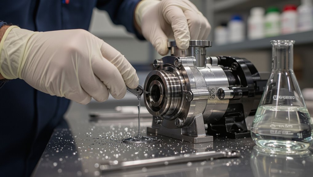
Cleaning a Grundfos pump means removing debris, mineral scale, and buildup from the impeller, seals, and internal passages to restore proper flow and sealing.
Indicators that cleaning is needed include reduced flow, unusual noise or vibration, increased energy use, and visible deposits when accessible.
Ignoring cleaning and descaling can lead to accelerated wear, sealing failures, cavitation, and premature pump replacement.
Signs your Grundfos pump needs cleaning
One clear indicator that a Grundfos pump requires attention is a noticeable drop in flow rate or water pressure, often accompanied by unusual noises, frequent cycling, or visible debris in strainers and filters.
These signs typically mean internal components such as impellers, seals, or housings are fouled by mineral buildup, sediment, or biological growth and need cleaning to restore proper operation.
Other cues include overheating, increased vibration, and tripped protections.
How to clean a Grundfos pump involves inspection, filter cleaning, descaling, flushing, and reassembly following manufacturer steps.
Risks of neglecting cleaning and descaling
A sustained decline in performance or repeated fault indicators often signals more than a temporary clog; neglecting routine cleaning and descaling allows mineral scale, sediment, and biological film to harden on impellers, housings, seals, and flow paths, which reduces efficiency, increases motor load, and shortens component life.
Left unchecked, leaks, cavitation, overheating, higher energy use, premature failures, and costly downtime become likely.
Safety precautions and tools needed before you start
Before beginning, the technician should confirm personal protective equipment and follow lockout/tagout procedures to isolate the pump and electrical sources.
A concise checklist of tools, approved cleaning chemicals, and likely replacement parts should be prepared.
Manufacturer guidance and warranty terms must be reviewed to guarantee approved methods and avoid voiding coverage.
Personal protective equipment and lockout procedures
Don appropriate personal protective equipment (PPE) and implement lockout/tagout procedures to eliminate hazards before servicing a Grundfos pump.
Wear chemical-resistant gloves, eye protection, and protective clothing.
Guarantee electrical isolation by locking and tagging disconnects, verifying zero energy with a tester.
Isolate fluid lines and relieve pressure.
Post warning signs and confirm authorized personnel control re-energization until work is complete.
Tools, chemicals, and replacement parts checklist
Checklist items guarantee the cleaning task proceeds safely and efficiently: insulated hand tools and non-sparking wrenches, a set of screwdrivers and hex keys sized for the pump fasteners, adjustable pliers, and torque wrench for reassembly;
chemical-resistant gloves, face shield, and apron for handling cleaning agents; a calibrated multimeter and voltage tester for final verification;
absorbent pads, spill kit, and containment trays for fluid control; compatible pump-safe cleaning solutions (non-chlorinated descalers, mild degreasers) and lubricants specified by Grundfos;
replacement gaskets, O-rings, shaft seals, and mounting hardware matching the pump model; and manufacturer’s manual, parts diagram, and lockout/tagout tags for reference.
- Essential tools
- Chemicals and PPE
- Replacement parts and documentation
Manufacturer recommendations and warranty considerations
When following Grundfos’ manufacturer recommendations and warranty requirements, technicians must verify model-specific service instructions and comply with lockout/tagout, electrical isolation, and pressure-relief procedures to prevent injury and voiding coverage.
Adherence to approved cleaning agents, torque settings, and part-replacement protocols preserves warranty eligibility.
Documentation of service, genuine parts use, and authorized repairs supports claims; unauthorized modifications or improper procedures may nullify coverage.
Prepare the pump and system for cleaning
Before cleaning, the pump must be isolated and the circuit drained to prevent spills and pressure-related hazards.
Relevant settings should be recorded and power disconnected to preserve system configuration and guarantee electrical safety.
A decision should then be made whether to remove the pump for bench servicing or perform cleaning in place, based on accessibility and condition.
Isolating the pump and draining the circuit
Isolate the pump from the system and fully de-pressurize the circuit before any cleaning begins.
Close isolation valves, tag them, and open a bleed or drain point downstream to remove trapped fluid.
Collect discharge safely in appropriate containers.
Verify zero pressure at test ports.
Confirm vents remain open until draining finishes, then reseal drains and prepare for the next maintenance step.
Recording settings and electrical disconnection
With the circuit depressurized and drains sealed, the technician documents current pump settings and prepares electrical isolation.
Pump nameplate, wiring diagram, control parameters, and VFD settings are recorded. Power is locked out and tagged per procedure; supply voltage is verified absent with a meter.
Ground continuity is checked.
Photographs of terminals and conduit routing supplement written records before proceeding with cleaning tasks.
Removing the pump from the system vs. in-place service
Decide whether the pump will be removed or cleaned in place based on accessibility, contamination level, and system complexity.
Removal suits heavy scaling, corrosion, or when seals/impellers require inspection; it allows thorough cleaning and parts replacement.
In-place service minimizes downtime for minor deposits, preserving piping integrity.
Document valves closed, drain points identified, and guarantee isolation and safe handling procedures before proceeding.
Step-by-step descaling and internal cleaning procedure
The procedure begins with a visual inspection of external components to remove loose debris and identify damage.
Next, the wet end is accessed to expose the impeller and volute for targeted cleaning.
The team then selects an appropriate descaler with proper dilution, applies it per safety and dwell-time guidelines, and uses mechanical methods where necessary to remove stubborn scale.
Inspecting external components and removing debris
Before opening the pump, visually inspect all external components—motor housing, electrical connections, pipe joints, and visible seals—for corrosion, residue, or mechanical damage, and note any loose fittings or buildup that could indicate internal scale.
Remove surface debris, wipe connections with a lint-free cloth, clear vent holes and strainers, tighten loose clamps, and photograph damaged areas for records before proceeding.
Accessing the wet end, impeller and volute
Access the wet end by isolating power and fluids, then relieving system pressure and draining the pump according to the manufacturer’s safety steps.
Remove casing bolts and separate the volute to expose the impeller. Inspect for scale, corrosion, and debris.
Carefully unfasten the impeller, noting orientation and shims. Clean mating surfaces, replace damaged seals, and reassemble using correct torque and alignment.
Choosing a descaling agent and dilution guidelines
Several common descaling agents—citric acid, dilute hydrochloric acid, and commercial pump-safe descalers—are suitable for Grundfos wet ends, each chosen for its effectiveness against specific deposits and compatibility with pump materials.
Selection depends on deposit type (carbonate, rust, organics) and elastomer compatibility.
Follow manufacturer dilution recommendations, start with mild concentrations, perform a compatibility test on spare parts, and document ratios and water temperature.
Applying chemical descaler safely and dwell times
Begin by isolating the pump from the system, draining residual fluid, and purging air so the wet end is accessible and safe to work on.
Apply the chosen descaler at specified dilution, filling the casing and passages. Observe manufacturer dwell times, typically 15–60 minutes, monitoring for reaction.
Rinse thoroughly with clean water, neutralize if required, and inspect seals and elastomers before reassembly and pressure testing.
Mechanical removal of scale and deposits
Disassemble the pump wet end and lay components on a clean surface. Then visually assess impeller, volute, diffuser, and shaft for scale, corrosion, or debris before selecting tools and methods for mechanical removal.
Use nylon brushes, plastic scrapers, and fine stainless-steel wire brushes gently; employ dental picks for crevices. Remove loose deposits, avoid gouging surfaces, and replace damaged seals or eroded parts as needed.
Rinsing, neutralizing chemicals, and checking for residue
Flush the wet end thoroughly with clean water to remove loose debris and dissolve remaining soluble residues before applying neutralizing agents.
After initial flushing, introduce a manufacturer-recommended neutralizer at proper dilution, circulate briefly, then purge.
Rinse repeatedly until pH and conductivity readings match supply water.
Visually inspect all cavities and seals for residue; repeat localized cleaning if deposits or discoloration persist.
Flushing the pump and system after descaling
After descaling, a controlled in-place flush is recommended to purge residual cleaner while preventing sudden pressure surges or contamination of downstream equipment.
If the pump was removed, reassemble carefully and perform a bench or system test run with fresh water to verify seals and internal clearances before returning to service.
Confirm that flow and pressure meet specifications and that no chemical odor or pH anomaly remains, indicating complete removal of descaling agents.
How to perform a controlled flush in-place
Begin by isolating the pump and system from the process lines and confirming all valves and bypasses are positioned to route rinse water through the pump only. This controlled configuration prevents contaminated solution from re-entering the process while allowing visual and sensor-based monitoring of effluent clarity and pH as descaling residues are expelled.
Start low-flow rinse, gradually increase to operating pressure, monitor until neutral pH and clear effluent. Then document results and secure valves.
Flushing when pump is removed: reassembly and test run
With the pump back on its mounting and all internal components reinstalled according to the manufacturer’s torque and alignment specifications, the technician reconnects suction and discharge piping, reopens isolation valves as required, and prepares for a controlled test run to confirm successful descaling.
They slowly refill and vent the system, inspect for leaks, run briefly to purge residual cleaning solution, then stop to verify seals and reassemble access points before normal operation.
Confirming flow, pressure, and absence of chemical residue
Once the pump has been reassembled, reconnected, and run briefly to purge the descaling solution, the technician proceeds to flush and verify system performance.
He measures flow and pressure against baseline specifications, inspects for steady, noise-free operation, and collects flush water samples.
pH and visual checks confirm no chemical residue.
Any deviations prompt additional flushing or component inspection before returning the pump to service.
Inspection and replacement of wear parts
A thorough inspection of the pump should assess the shaft seal, bearings, and O-rings for wear or damage before reassembly.
The technician must know when to replace the impeller, wear rings, and seals to restore performance and prevent leaks.
Reassembly requires correct torque values and sequence to guarantee proper alignment and long-term reliability.
Checking shaft seal, bearings, and O-rings
Several components—the shaft seal, bearings, and O‑rings—require careful inspection because their failure typically leads to leaks, noise, or reduced pump performance.
Visually inspect seals and O‑rings for cracks, flat spots, or swelling. Spin the shaft to detect rough or noisy bearings.
Replace any compromised parts with OEM or compatible replacements, lubricating bearings per specifications and reseating O‑rings to guarantee proper sealing.
When to replace impeller, wear rings, and seals
Inspecting seals, bearings, and O‑rings often reveals wear patterns that indicate whether other flow‑path parts need attention. The impeller, wear rings, and mechanical seals should be examined next for loss of material, deformation, or corrosion.
Replace impellers with warped blades, erosion, or imbalance. Swap wear rings when radial clearance exceeds manufacturer limits. Renew mechanical seals on leakage, scoring, or hardening for reliable sealing.
Torque and reassembly best practices
Begin reassembling with controlled torque sequences and verified part orientation to guarantee sealing integrity and rotational balance.
Technicians should follow manufacturer torque charts, use calibrated tools, and apply threadlocker where specified.
Replace worn gaskets, seals, and wear rings before final assembly.
Verify shaft runout and clearances, tighten fasteners in star patterns, and perform a low-speed spin test to confirm smooth operation and absence of leaks.
Recommissioning and performance verification
After cleaning and replacing any wear parts, the pump is reconnected electrically and the system pressure is restored to operational levels.
Initial startup checks should confirm normal vibration, noise, temperature, and flow before leaving the unit unattended.
All post-cleaning performance readings are recorded to establish a new baseline for future comparisons.
Reconnecting electrical and restoring system pressure
Reconnecting the electrical supply and restoring system pressure requires a methodical sequence to guarantee safe recommissioning and accurate performance verification.
The technician isolates power, inspects wiring and terminal integrity, tightens connections, then re‑energizes controls per manufacturer’s procedure.
Valves are opened slowly, venting trapped air and monitoring gauge rise.
Final checks confirm stable pressure, absence of leaks, correct control responses, and documented readings.
Startup checks: vibration, noise, temperature, and flow
A systematic series of startup checks verifies that vibration, noise, temperature, and flow are within acceptable limits before returning the pump to regular service.
The technician observes vibration levels with a meter, listens for unusual sounds, monitors bearing and casing temperatures, and confirms flow and pressure meet specifications.
Any deviations prompt shutdown, inspection, coupling alignment, or re-torqueing before repeating checks.
Recording post-cleaning performance and baseline data
With startup checks confirming acceptable vibration, noise, temperature, and flow, attention shifts to documenting post-cleaning performance and establishing a new baseline for the pump.
Technicians record flow rate, pressure, power draw, and motor current under defined operating points. Log timestamps, cleaning actions, and test conditions.
Compare against pre-cleaning metrics, note deviations, and schedule follow-up inspections or adjustments as required.
Preventive maintenance schedule and water treatment recommendations
A preventive maintenance schedule should specify routine cleaning intervals tailored to the pump’s application and local water quality to prevent buildup and loss of efficiency.
Complementary measures such as filtration, softening, and appropriate chemical dosing are recommended to reduce scaling and corrosion.
Regular monitoring of flow, pressure, vibration, and conductivity helps detect issues early and extend pump life.
Routine cleaning intervals by application and water quality
Because operating conditions and source-water chemistry vary, cleaning frequency for Grundfos pumps should be based on application type and water quality rather than a fixed calendar interval.
High-mineral, abrasive, or biologically active supplies require monthly to quarterly inspections and cleaning.
Moderate domestic or irrigation systems typically need semiannual checks.
Low-risk, treated water installations may be serviced annually, with records guiding adjustments.
Filtration, softening, and chemical dosing to reduce scaling
Selecting appropriate water treatments complements the inspection schedule by preventing the mineral buildup and biofouling that drive more frequent cleanings.
Implement pre-filtration to remove particulates, ion exchange or reverse osmosis for hardness reduction, and controlled chemical dosing (antiscalants, biocides, pH adjusters) per water analysis.
Establish dosing rates, service intervals, and recordkeeping to minimize scaling while avoiding corrosion and chemical overuse.
Monitoring tips to extend pump life
Implement a structured monitoring program that combines scheduled inspections, simple field tests, and trend logging to detect issues before they cause pump failure.
Inspect seals, bearings, and impellers monthly; record vibration, flow, pressure, and amperage.
Calibrate sensors quarterly.
Maintain water chemistry within specified hardness, pH, and conductivity limits; apply softening or inhibitors as required.
Review logs and adjust maintenance intervals based on trends.
Common problems, troubleshooting, and solutions
After cleaning, persistent clogging or reduced flow may indicate retained debris, impeller damage, or inlet restrictions that require targeted troubleshooting.
Leaks, seal failures, and unusual noises following service often point to improper reassembly, worn components, or cavitation and should be inspected promptly.
If basic checks and corrective steps do not restore normal operation, contact a qualified technician or Grundfos support for diagnostics and repair recommendations.
Persistent clogging or reduced flow after cleaning
Investigate persistent clogging or reduced flow as a sign that initial cleaning missed debris, damage, or systemic issues rather than as an isolated, resolved problem.
Inspect inlet strainers, impeller vanes, and seals for remaining sediment, corrosion, or wear.
Verify suction conditions, check for airlocks and blocked discharge lines, and test pump curves against expected performance.
Replace damaged components and repeat targeted cleaning or flow diagnostics.
Leaks, seal failures, and unusual noises after service
Listen for and inspect signs of leaks, seal failures, or unusual noises immediately after service, as they often indicate installation errors, worn components, or residual debris rather than normal settling.
Check mechanical seals, O‑rings, and housing bolts for tightness and correct seating.
Flush residual debris, retorque connections to spec, replace damaged seals, and run the pump at low speed to verify quiet, leak‑free operation.
When to call a professional or contact Grundfos support
When should a technician be called, or Grundfos support contacted, depends on symptom severity, safety risk, and troubleshooting limits.
Immediate contact is advised for leaks, electrical faults, persistent cavitation, overheating, or failure after standard cleaning.
Schedule professional service for complex seal replacements, motor issues, or unclear diagnostics.
Provide model, serial, symptoms, and steps already taken to expedite accurate guidance and repair.
Quick reference: cleaning checklist and safety reminders
Start with a brief pre-cleaning safety check and a simple, itemized checklist that personnel can follow at a glance; it should include PPE requirements, lockout/tagout confirmation, electrical isolation verification, and confirmation that the pump and system are depressurized and drained.
Personnel should verify tools, chemicals, and manuals, then proceed methodically.
- Confirm PPE and isolation.
- Drain, vent, label.
- Inspect seals, retain parts.
Comparison of cleaning methods and when to use each
With safety checks and isolation confirmed, personnel should choose a cleaning method based on pump condition, contamination type, and site constraints. Mechanical brushing suits light deposits; chemical descaling removes heavy limescale; flushing clears debris after repairs; ultrasonic or professional service tackles internal damage. Select lowest-risk effective option and document chemical compatibility.
| Method | Best use case |
|---|---|
| Brushing | Light deposits |
| Chemical | Heavy limescale |
| Flushing | Debris removal |
| Professional | Internal damage |
Conclusion
After following meticulous steps to remove scale, flush chambers, and restore seals, the Grundfos pump will miraculously behave like new—until the next mineral uprising. Regular maintenance, proper inhibitors, and timely inspections, purportedly dull chores, are actually the heroic acts that keep systems from collapsing into sluggishness and leaks. So continue the tedious ritual of care: it defeats corrosion, preserves efficiency, and spares one from the dramatic thrill of emergency breakdowns.