Pipe Invert Explained: What It Is & Why It Matters for Plumbing
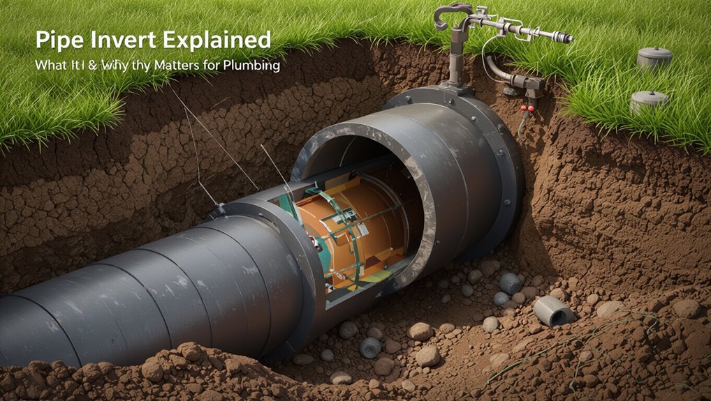
The pipe invert refers to the inside bottom elevation of a pipe that is crucial for ensuring proper gravity flow in plumbing systems. It serves as a reference point for calculating slope, capacity, and connections for sewers and drains. Accurate invert levels are essential for determining trench depth, bedding, and manhole placements, which help prevent issues such as pooling, backups, or surcharging. On plans, inverts are typically indicated as INV or EL and must align with the project datum. For effective management, continue reading for practical tips on how to measure, interpret, and address any invert-related issues.
What Pipe Invert Means : Quick Definition and Why It Matters
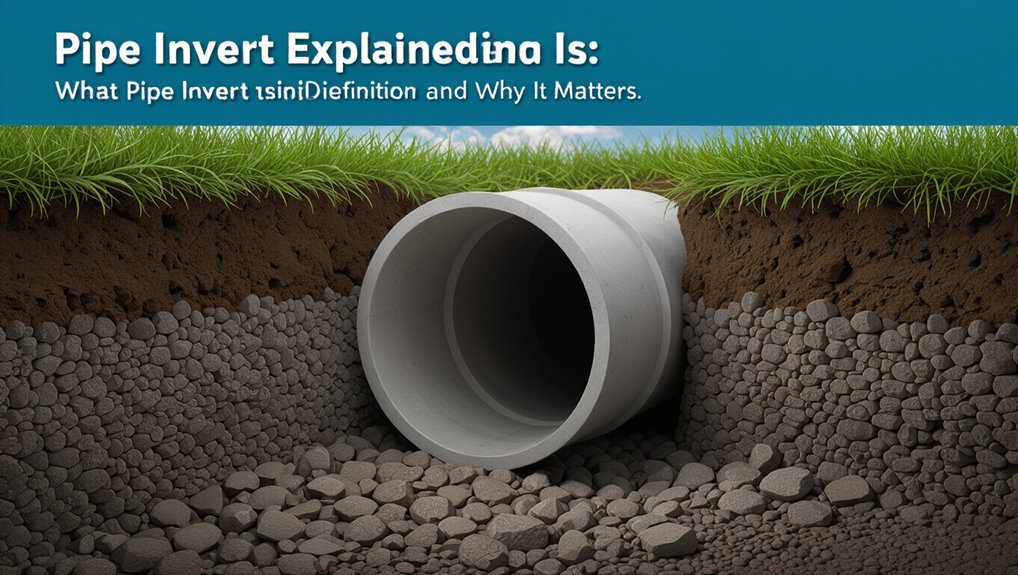
In the context of drainage and sewer design, the pipe invert is the lowest internal point of a pipe’s cross-section and serves as the reference elevation for flow. The invert determines hydraulic gradient, affects velocity, and governs capacity calculations for stormwater and sanitary systems.
Designers use invert elevations to set slopes, coordinate connections between pipes and structures, and guarantee self-cleansing velocities while preventing backflow. Accurate invert data informs trench depth, bedding, and manhole placement.
Misjudged inverts can cause surcharging, reduced capacity, or maintenance difficulties. Consequently, the invert is fundamental to conveyance performance, constructability, and long-term system reliability.
What “Pipe Invert” Means in Plain Language
The invert elevation is the vertical position of the inside bottom of a pipe where fluid flows.
It determines flow direction, slope, and connection alignment in drainage and sewer systems.
Understanding this simple measurement helps guarantee proper flow, prevent backups, and coordinate construction elevations.
Invert Elevation Defined
What exactly is an invert elevation? It denotes the vertical position of a pipe’s lowest interior surface relative to a reference datum, typically sea level or a site benchmark.
Engineers record invert elevation at manholes, storm drains, and sewer runs to define pipe grades and connect points.
The measurement is taken inside the pipe at the invert line, not the pipe crown or outside bedding.
Notation often appears on drawings as “INVERT = +X.XX” or similar.
Accurate invert elevations guarantee continuity between structures and enable calculation of slope, flow capacity, and proper alignment during installation.
Why It Matters
When considered in everyday terms, a pipe invert is simply the inside-bottom level of a pipe that determines where water or waste will flow and how fast.
It matters because invert elevation controls slope, ensuring gravity moves sewage and stormwater steadily without pooling or backing up. Proper invert placement prevents blockages, reduces odor risks, and minimizes wear from sediment and turbulence.
It governs connections between fixtures, manholes, and mains, affecting maintenance access and pump requirements. Accurate invert data informs designs, inspections, and repairs; small errors can cause flooding, costly rework, or regulatory noncompliance, so precision in invert measurement is essential.
How Invert Differs From Pipe Crown and Flowline
In pipe terminology, the invert refers to the lowest internal point of the pipe wall, distinct from the crown (the highest interior point) and the flowline (the path followed by the moving fluid).
The invert is a fixed geometric reference used for grading, bedding, and alignment. The crown marks elevation limits and clearance; it is opposite the invert. The flowline denotes where fluid naturally travels within the conduit and can shift with flow conditions, slope, and obstructions.
Engineers reference invert for capacity calculations, maintenance access, and interfacing multiple pipes; crown and flowline inform structural cover, hydraulic behavior, and inspection priorities.
How to Read Invert Elevations on Engineering Drawings
Having established the invert as the fixed lowest point of a pipe interior, the next step is interpreting how that elevation is shown on engineering drawings.
Drawings present invert elevations as numeric values at pipe nodes and manholes, typically tied to a project datum (e.g., NAVD88).
Read labels adjacent to pipe lines or structure symbols; they indicate invert elevation at entry and exit points.
Note whether values represent top or bottom of pipe by context and section views.
Cross-reference profiles for longitudinal slope and chainage.
Verify units and datum, and confirm consistency between plan view, profile, and details before finalizing construction elevations.
Common Invert Abbreviations and Symbols on Plans
The section outlines common plan abbreviations used for invert elevations and the standard symbols that accompany them.
It explains how abbreviations like “INV,” “Ø,” and “EL” are placed on drawings and what information they convey.
Clear symbol interpretation helps prevent misreading of pipe depths and flow directions on plans.
Common Plan Abbreviations
On construction drawings, common plan abbreviations and symbols convey invert elevations and related pipe information succinctly; understanding them prevents misinterpretation during layout and inspection.
Typical abbreviations include INV (invert), EL (elevation), TOS/TOP (top of structure), FL (flow line), CL (centerline), DIA (diameter) and S/ (slope) or % for gradient. Notations often pair INV with numeric values (e.g., INV=3.25) or stationing (STA 12+34).
Manholes, cleanouts and inlets use standard tags (MH, CO, IN).
Recognizing these conventions streamlines coordination between designers, surveyors and installers and reduces errors in field execution.
Symbol Interpretation Guide
How should a reader quickly decode the compact symbols that annotate pipe inverts, slopes, and structure details on plans? The guide catalogs common abbreviations: INV for invert elevation, FT/IN for feet and inches, Ø for diameter, S or % for slope, CL for centerline, MH for manhole, CB for catch basin, and EL or ELEV for elevation benchmarks.
Numeric strings like 4.25 INV or 12% S denote precise invert level and gradient. Arrows indicate flow direction; triangular or circled tags mark reference points. A legend and consistent notation on each plan sheet guarantee accurate interpretation and coordination.
Tools You Need to Measure Invert Elevation in the Field
For accurate invert elevation measurements in the field, a compact kit of precise instruments is essential: a level or total station for establishing a datum, a grade rod or staff for reading elevations, a reliable tape measure for distances along the pipe, and handheld surveying accessories like tripods, prism poles, and spirit levels to guarantee stable setup and consistent reads.
Additional useful items include a digital inclinometer for slope checks, chalk or markers for pipe reference points, protective gloves, and a flashlight for confined spaces.
Calibration tools, spare batteries, and a field notebook complete a practical set for reliable, repeatable invert data collection.
Step‑By‑Step: Taking an Invert Measurement With a Level
The procedure begins with positioning and leveling the instrument on stable ground directly over or adjacent to the pipe run.
Once the level is set, the operator sights the staff at the pipe invert and records the rod reading. That reading is then converted to the invert elevation using the known instrument height and reference datum.
Setting Up The Level
Before taking measurements, the level must be set on a stable surface and checked for calibration to guarantee accurate invert readings. The technician places the level parallel to the pipe run, secures it against vibration, and confirms the bubble or electronic indicator centers.
Tripod feet or a flat board prevent tilt; weights or clamps stabilize in wind. Alignment pins or marks reference fixed points on the pipe to reproduce positions. Protective padding avoids scratching seals. Verify zero after each reposition.
Record level model, serial number, and calibration date to make certain traceability and repeatability of subsequent invert measurements.
- Tripod and bubble centered
- Alignment marks on pipe
- Calibration tag visible
Reading The Invert Height
With the level secured and calibrated as previously described, the technician positions the instrument over the reference point and sights to the pipe invert using the level’s eyepiece or digital readout. They record the vertical staff reading or on-screen elevation at the invert sightline, ensuring the staff is plumb and the line of sight unobstructed.
Multiple readings along the pipe length are taken to confirm consistency and detect slope. Corrections for instrument height above reference are applied, and any offset from the centerline is noted.
Results are documented with location, date, and conditions for later hydraulic and construction use.
Finding Pipe Invert With a Laser Level
Using a laser level, a surveyor can quickly determine a pipe’s invert elevation by projecting a precise horizontal reference and measuring the vertical difference to the pipe’s lowest internal point.
The technician sets the laser on a tripod, aligns to a known benchmark, then sights into the manhole or cleanout.
A rod or target is lowered to touch the invert, and the vertical reading gives the invert elevation when referenced to the laser plane.
Notes about obstructions, water level, and access points are recorded.
Results are used for grade verification and as-built documentation.
- tripod-mounted laser over benchmark
- target lowered to invert
- recorded elevation reading
Accuracy and Tolerances for Laser Invert Measurements
Laser invert measurements are constrained by the resolution limits of the laser instrument and the practical ability to read and record small vertical changes.
Acceptable accuracy is consequently defined by specified tolerance bands that account for instrument resolution, setup error, and site conditions.
The following discussion compares typical resolution values to common permissible tolerances used in pipe installation and inspection.
Measurement Resolution Limits
In evaluating pipe invert measurements, resolution defines the smallest change in elevation that the instrument can reliably detect and report. Measurement resolution limits determine whether subtle slope variations are visible, influence survey spacing, and affect confidence in as-built records. Instruments with finer resolution reveal micro-gradients; coarser units may mask deviations that impact flow. Practitioners select equipment and procedures to match project sensitivity, documenting instrument spec and environmental factors that can degrade effective resolution.
- A laser device showing 0.1 mm steps resolving subtle crown-to-invert differences.
- A 1 mm resolution masking minor sagging over long runs.
- Aggregated readings smoothing local variations.
Permissible Tolerance Bands
For pipe invert measurements, permissible tolerance bands define the allowable deviation between measured elevations and design or nominal inverts, expressed as absolute values or percentage gradients.
These bands guide acceptable laser survey error, construction acceptance, and maintenance decisions.
Tolerances vary by pipe diameter, material, flow requirements, and regulatory standards; tighter bands apply to steep gradients or gravity sewers.
Measurement procedures should state instrument accuracy, environmental influences, and data processing methods to guarantee compliance.
Deviations outside bands trigger remediation, re-survey, or adjustment.
Clear documentation of tolerance criteria preserves asset performance, reduces hydraulic risk, and aligns stakeholders on acceptable measurement uncertainty.
Calculating Invert From Manhole Rim and Bench Elevations
When determining a pipe invert elevation from manhole data, the bench (shelf) elevation and the rim (top) elevation provide the necessary reference points to compute the internal flow level.
The process subtracts the vertical drop from rim to bench, then applies the known offset from bench to invert (pipe invert depth).
Verify units and datum consistency.
Record measurements and rounding conventions to maintain design tolerances.
Visualizing section and measuring offsets reduces errors, enabling accurate hydraulic profile and maintenance planning.
- Rim surveyed point above ground.
- Bench ledge inside channel.
- Offset measured to pipe crown.
Calculating Invert for Sloped Pipe Runs
Calculating an invert for a sloped pipe run requires projecting the downstream or upstream elevation along the pipe grade and applying the pipe’s internal offsets to determine the flowline elevation at each structure.
The process uses known rim, bench, or flowline points and the run’s slope to interpolate invert elevations at intermediate structures.
Measurements account for pipe diameter, wall thickness, and bedding offsets to locate the internal flowline.
Elevations are adjusted for sag, rise, or changes in grade between structures.
Results verify hydraulic continuity, assure positive flow, and provide clear elevations for construction staking and as-built documentation.
Minimum Invert Slopes Required for Common Pipe Sizes
Minimum invert slope requirements vary by pipe material, diameter, and purpose, and they set the shallowest gradient that will maintain self-cleansing flow and prevent sedimentation.
Typical guidance lists minimum slopes: smaller diameters need steeper gradients to move solids; larger mains can run flatter. Designers consult codes and manufacturer data: for example, 3/4–1¼” often require 1/4″ per foot, 2–3″ around 1/8″ per foot, and 6″ and above sometimes 1/16″ per foot, adjusted for flow, temperature, and fluid viscosity.
Practical planning balances constructability with hydraulic need.
- Narrow residential branch
- Medium building drain
- Large sewer main
Why Too‑Flat an Invert Causes Blockages
Frequently, drains with excessively flat inverts fail to develop enough velocity to carry solids and settled materials downstream, so particles settle, accrete, and form obstructions.
Reduced flow energy allows grit, grease, and fibrous waste to adhere to pipe walls; repeated deposition narrows the bore and further slows flow.
Intermittent flows exacerbate buildup because short surges cannot re-suspend deposits.
Sediment pockets form at low points or joints, creating initiation sites for blockages.
Maintenance becomes more frequent and costly as mechanical cleaning or hydro-jetting is required.
Proper invert slope prevents persistent deposition by maintaining self-cleansing velocities appropriate to the waste type.
Why Too‑Steep an Invert Causes Erosion and Air Pockets
A steep invert increases flow velocity, which raises the potential for sediment scouring along the pipe bed.
That higher velocity can mobilize and carry abrasive particles, accelerating erosion of joints and lining.
Rapid flow and turbulence also promote air pocket formation as entrained air separates from the water and collects at high points.
Increased Flow Velocity
Often, a steeper invert increases flow velocity, which raises the risk of internal erosion and scour at joints and bends.
Higher speeds concentrate shear stress on pipe walls, loosening mortar, coatings, or softer materials. Turbulent wakes form downstream of fittings, accelerating wear and promoting short‑duration cavitation where vapor pockets collapse against surfaces.
Rapid flow also traps and transports air into pockets at grade changes, causing flow interruptions and hammering.
Designers balance slope to maintain self‑cleansing without excess velocity.
Visualize common consequences:
- Jetting flow at a lateral joint eroding bedding.
- Whirlpools behind a bend scouring the crown.
- Air pocket trapping at a sudden drop.
Sediment Scouring Risk
Steep inverts accelerate flow enough to mobilize and transport bed material, producing concentrated shear at changes and fittings that erodes bedding and pipe walls.
This scouring removes fine and coarse particles, undermining support and inducing differential settlement or misalignment.
Exposed joints and bedding voids open as material is flushed downstream, increasing infiltration pathways and load concentrations.
Repeated scour enlarges internal profiles, alters hydraulic capacity, and promotes collapse where wall material is weakened.
Predictable locations include bends, inlets, drops, and constrictions.
Mitigation relies on grading to acceptable slopes, energy dissipation measures, protective linings, and periodic inspection and sediment management.
Air Pocket Formation
When flow velocities increase because an invert is too steep, water can detach from the pipe crown or fittings and trap pockets of air downstream of high-energy zones. Air pockets reduce conveyance, cause hammer-like pressure surges when compressed and released, and promote localized turbulence that accelerates erosion at welds, joints, and bedding interfaces. Operators may observe fluctuating flow, noise, or repeated backups.
Mitigation includes grade adjustment, strategic venting, and flow control to maintain subcritical velocities. Visualize:
- A sluice where a vapor gap forms beneath a fast-moving stream.
- Bubbles wedged under a pipe crown, starving flow area.
- Pulsing surges striking a joint.
Sanitary Sewer Invert: Slope, Cover, and Sag/Crest Controls
Design of the sanitary sewer invert balances slope, cover, and sag/crest control to guarantee reliable gravity flow while preventing infiltration, surcharging, and maintenance access issues.
Engineers set minimum and maximum slopes to maintain self-cleansing velocities without causing excessive erosion or backups.
Adequate cover protects against loads and frost but must avoid excessive depth that complicates access and increases costs.
Sag locations require low-point drains, venting, or extra slope to prevent pooled solids; crests need smooth changes to avoid air locks and flow separation.
Material selection, bedding, and alignment are coordinated to meet hydraulic, structural, and operational requirements.
Stormwater Drainage Invert Priorities
For stormwater systems, invert selection prioritizes achieving the lowest practical elevation to maximize gravity drainage and reduce pumping needs.
Equally important is preserving continuous flow paths to prevent ponding and guarantee efficient conveyance.
Maintenance access is then balanced against these objectives, with inverts set to allow inspection and cleaning without compromising hydraulic performance.
Lowest Practical Elevation
In setting stormwater pipe inverts, the guiding principle is to place them at the lowest practical elevation that still maintains hydraulic capacity, prevents backflow, and respects constructability constraints.
The lowest practical elevation minimizes ponding, maximizes gravity drainage, and balances excavation depth against maintenance access and bedding requirements. Designers consider existing ground, outlet elevation, and future sediment accumulation when choosing invert depths.
Practical limits include cover requirements, utility conflicts, and constructibility equipment reach.
Visualizing trade-offs helps decision-making:
- A shallow invert near surface with easy access but limited slope.
- A mid-depth invert balancing slope and excavation.
- A deep invert maximizing slope yet increasing costs.
Flow Path Continuity
Having established the practical limits for invert depth, attention turns to maintaining continuous flow paths between inlets, conveyance pipes, and outlets so that stormwater moves by gravity without unintended ponding or backflow.
Flow path continuity prioritizes consistent downstream slope, alignment of invert elevations at junctions, and avoidance of low spots where sediment or debris can accumulate.
Designers coordinate inlet rim heights, pipe diameters, and flap or check valves to preserve unimpeded gravity flow while accommodating peak discharge. Hydraulic modeling verifies velocity and freeboard to prevent surcharging.
Continuity considerations also address changes between different materials and accommodate future downstream capacity constraints.
Maintenance Access Priority
With maintenance access prioritized, drain invert decisions favor configurations that allow safe, efficient inspection, cleaning, and repairs without extensive excavation.
The invert profile emphasizes accessible manholes, rodding points, and gradual slopes that prevent sediment traps.
Designers balance hydraulic performance with practical service needs, placing inverts at heights that align with surface access and equipment reach.
Material selection and joint layout also reflect maintenance frequency, reducing obstruction risk and enabling non-destructive interventions.
Clear records of invert elevations assist future crews in locating trouble spots quickly, minimizing downtime and cost while preserving drainage function.
- Manhole-aligned inverts lowering tool angles.
- Gradual slopes avoiding sediment pools.
- Accessible rodding points near surface.
Invert Planning for Combined Sewer Systems
For combined sewer systems, invert planning directs the vertical placement of pipe bottoms to balance hydraulic capacity, constructability, and maintenance access. Engineers calculate slopes to convey peak combined flows while preventing sedimentation and ensuring manhole alignments. Depth choices affect pump requirements, trenching logistics, and coordination with storm and sanitary branches. Long-term performance relies on predictable self-cleansing velocities and access points for inspection and cleaning. Risk assessments inform invert elevation relative to groundwater and adjacent utilities. Typical considerations include future capacity upgrades, emergency overflow routing, and rehabilitation feasibility to minimize service disruptions and lifecycle costs.
| Consideration | Impact | Mitigation |
|---|---|---|
| Slope | Flow velocity | Grade control |
| Depth | Construction cost | Staging plans |
| Access | Maintenance ease | Manhole spacing |
Invert Placement in House Plumbing Versus Public Mains
The article contrasts invert placement in private house plumbing with that in public mains, noting typical differences in invert depth and how municipal systems often run deeper to accommodate larger flows and cover.
It also highlights differing pipe slope requirements: steeper slopes in building drains versus milder gradients in trunk mains to balance self-cleansing velocity and hydraulic capacity.
Finally, access for maintenance is compared, with house systems relying on confined cleanouts and public mains designed with manholes and serviceability clearances.
Invert Depth Differences
Compared to house plumbing, public mains are typically set at much greater invert depths to accommodate larger flow volumes, maintain required gradients over long runs, and protect against freezing and surface loads.
The invert depth difference reflects engineering priorities: residential lines follow building layouts and shallow trenches for easy access, while mains require deeper bedding, heavier cover, and coordination with other utilities.
Deeper inverts also reduce infiltration risk and allow larger diameters without raising surface profiles.
Design choices balance cost, maintenance, and resilience.
Visualize these contrasts:
- Shallow backyard lateral near foundation.
- Deep city main beneath roadway structure.
- Trench with layered bedding and heavy cover.
Pipe Slope Requirements
Shifts in invert depth naturally lead to different slope expectations for house plumbing versus public mains.
House drains require steeper slopes to guarantee self-cleansing flows over short runs—typically 1/4 inch per foot for 1¼–3 inch pipes and 1/8 inch per foot for larger residential drains.
Public mains, conversely, use gentler, calculated gradients to accommodate long distances, varied flows and maintenance equipment, often governed by municipal standards.
Engineers balance invert placement, slope and pipe diameter to prevent stagnation, surcharge or excessive velocities.
Design prioritizes hydraulic performance, constructability and regulatory compliance rather than uniform slope across systems.
Access For Maintenance
In considering access for maintenance, invert placement in house plumbing tends to prioritize ease of reach for routine clearing and trap access, while public mains emphasize long-term serviceability for crews and equipment.
The house invert is shallow, near cleanouts and under fixtures for quick snaking; mains sit deeper with gradual grades to allow vacuum trucks and manhole access. Designers balance slope, depth, and junction locations to minimize excavation and downtime.
Emergency access points and inspection chambers reflect this divergence, ensuring small-scale convenience versus large-scale durability and safe worker access.
- Basement cleanout near shallow invert
- Yard cleanout linking to deeper main
- Manhole serving deep, sloped trunk line
Why Invert Matters for Pump Station Inlets
When located at a pump station inlet, the pipe invert establishes the hydraulic grade and directly affects suction conditions, net positive suction head (NPSH), and the risk of air entrainment or vortexing.
Proper invert elevation guarantees sufficient submergence to prevent cavitation and maintain continuous flow into pump intakes.
Incorrect inverts can create low-pressure zones, swirling flows, or drawdown that reduce pump efficiency and increase wear.
Consistent slope and alignment minimize sediment accumulation and hydraulic disturbances.
Coordination with pump characteristics and anticipated operating levels guides invert selection to preserve reliable performance, reduce maintenance, and extend equipment life.
Designing Inverts for Catch Basins and Inlet Structures
When designing inverts for catch basins and inlet structures, engineers prioritize accurate invert elevation selection to guarantee proper gravity flow and prevent ponding.
Alignment with incoming and outgoing flow paths is evaluated to minimize turbulence and sediment deposition.
Structural access requirements are also considered to allow inspection, maintenance, and safe personnel entry.
Invert Elevation Selection
How should the invert elevation be chosen to guarantee reliable flow into catch basins and inlet structures? The invert elevation is set to assure gravity-driven entry, prevent ponding, and allow debris passage without blockages. Designers reference hydraulic grade lines, expected minimum flow depths, and upstream grades when specifying elevations. Consider freeboard for surcharge events and maintenance access for sediment removal.
- Align invert below surrounding surface to promote capture during normal flow.
- Maintain sufficient slope upstream to avoid standing water while preventing excessive velocity.
- Set invert above downstream tailwater to avoid backwater intrusion and promote draining.
Flow Alignment Considerations
Following invert elevation selection, attention shifts to aligning flow into catch basins and inlet structures so incoming runoff follows a controlled path into the opening rather than striking gratings or corners.
Designers position inverts to guide velocity vectors toward the throat, minimizing turbulence and sediment deposition.
Smooth transitional slopes and curvature reduce energy losses and prevent scour at inlet edges.
Hydraulic grade and approach channel geometry are matched to inlet capacity to avoid overtopping.
Skew angles are limited to reduce asymmetric flow and localized erosion.
Routine modeling and inspection ensure alignment performs under variable flows, preserving conveyance efficiency and prolonging basin functionality.
Structural Access Requirements
In addressing structural access requirements, invert design must balance hydraulic performance with safe, maintainable entry to catch basins and inlet structures. Considerations include invert depth relative to cover, slope continuity to prevent sediment entrapment, and access opening alignment for inspection tools. Materials, corrosion protection, and benching shape affect long-term serviceability. Coordination with load-bearing frames and grates guarantees structural integrity under traffic.
Clearances for confined-space entry, ladder or step provisions, and lifting points for covers reduce risk during maintenance.
- Round grate centered over smooth bench to guide flow.
- Stepped access with anti-slip rungs.
- Reinforced frame resisting live loads.
Invert Layout for Sewer Laterals and Building Connections
For sewer laterals and building connections, the invert layout defines the vertical positions and slopes of pipe crowns and inverts so wastewater flows by gravity without surcharge or backflow.
It specifies entry and exit invert elevations at property lines, cleanouts, and building connection points, ensuring minimum slope is met while maintaining adequate depth for frost protection and cover.
The layout coordinates with service pipe size, alignment, and existing mains to prevent conflicts and permit proper access for inspection.
Designers check as-built grades, catchment elevations, and local codes, adjusting bends or offsets to preserve hydraulic capacity and facilitate maintenance.
How Invert Impacts Manhole Benching and Slope
Manholes require careful invert placement because the relative elevations and slopes of incoming and outgoing pipes dictate benching geometry and flow patterns.
Proper invert alignment concentrates flow, preventing pockets and guiding debris through the channel.
Manhole benching slopes shift between pipe inverts, control turbulence, and allow maintenance access.
Designers set bench profiles to match invert elevations while preserving minimum slope for self-cleansing.
Incorrect invert offsets cause standing water, scour, or backflow into branches.
Consider hydraulic continuity, maintenance safety, and construction tolerances when specifying benching tied to inverts.
- Smooth bench channel curving to match invert alignments.
- Stepped bench for varied pipe elevations.
- Sloped bench directing flow to outlet.
Adjusting Invert When Connecting Pipes of Different Diameters
When connecting pipes of different diameters, the invert elevations must be aligned to guarantee a smooth hydraulic changeover.
Careful adjustment controls flow velocity to prevent scour in smaller pipes or surcharging in larger ones.
The changeover slope and length are specified to minimize turbulence and preserve capacity.
Aligning Invert Elevations
Connecting pipes of different diameters requires careful adjustment of invert elevations to maintain flow efficiency and prevent turbulence or backwater effects. Alignment guarantees smooth progression, minimizes sediment traps, and preserves hydraulic grade.
Installers set the smaller pipe invert slightly lower or use tapered fittings so the flow line slopes continuously. Inspection chambers or drop structures accommodate vertical offsets where space or grades constrain alignment.
Joining methods—bell-and-spigot, flexible couplings, or fabricated reducers—must respect the established invert to avoid steps. Proper surveying and temporary shimming during assembly prevent misalignment and shorten corrective excavation.
Regular verification preserves long-term system performance.
- Tapered reducer seating
- Drop manhole detail
- Invert level check
Managing Flow Velocity
Adjusting invert elevations to line up differing pipe diameters also affects flow velocity and requires deliberate recalibration of slope and cross‑sectional area.
When a larger pipe feeds a smaller one, velocity increases; when a smaller feeds a larger, velocity decreases.
Designers must calculate new velocities to avoid scour, sedimentation, or reduced self‑cleansing.
Continuity and energy principles guide adjustments: maintain acceptable Reynolds numbers and shear stress ranges for the conveyed fluid.
Practical measures include modest slope changes, use of expansion or contraction fittings, and verifying velocities against codes.
Documentation should record pre‑ and post‑connection hydraulics to safeguard long‑term performance.
Transition Slope Details
In transitions between differing pipe diameters, the invert slope must be detailed to control energy changes and flow distribution while preventing localized turbulence or sediment traps. The engineer specifies gradual slope adjustments, aligning invert elevations to maintain target velocity and avoid backwater.
Hydraulic calculations determine where to steepen or flatten slope to preserve self-cleansing conditions. Structural supports and bedding follow the adjusted invert to prevent settlement.
Inspection points and access fittings are placed where slope changes to monitor deposition. Clear documentation guarantees installers set invert elevations precisely, minimizing retrofit corrections and preserving system performance.
- Narrowing: increasing slope, accelerating flow.
- Widening: easing slope, reducing scour.
- Offset: stepped invert, controlled transition.
Solving Invert Conflicts When Utilities Cross
When underground pipes cross, conflicting inverts commonly occur where one utility’s flowline is higher than the other’s required clearance, necessitating careful coordination of grades, fittings, and encasements to maintain hydraulics and structural integrity.
Resolution begins with accurate survey data and utility records to identify vertical constraints. Options include lowering or raising inverts within allowable slopes, adding short-radius fittings, using depressed crossings with protective encasement, or rerouting portions of conduit.
Structural analysis ensures adjacent pipe loads are supported. Coordination among owners, adherence to codes, and documenting revised as-builts finalize the solution while minimizing service disruption and preserving hydraulic function.
How Bedding and Embedment Change the Pipe’s Effective Invert Elevation
Resolving invert conflicts through grade changes or encasements does not end the vertical-control story: the bedding and embedment materials around a buried pipe alter its true flowline elevation and structural behavior. Compaction, settlement, and bedding thickness all shift the effective invert relative to surveyed marks.
Designers specify granular bedding, haunch fill, and initial cover to control deformation and maintain hydraulic slope; contractors must place and compact to tolerances. Inspection verifies as-built invert matches design intent, accounting for potential post-construction settlement.
Practical coordination between geotechnical, civil, and construction teams preserves capacity and prevents unexpected low spots or surcharge.
- Narrow trench, dense bedding
- Loose backfill, uneven haunches
- Controlled compaction, monitored elevation
Handling Invert With Flexible Versus Rigid Pipes
Between flexible and rigid pipe systems, invert handling hinges on how each responds to soil loads and support conditions.
Flexible pipes (PVC, HDPE) rely on soil-structure interaction; effective invert elevation depends on uniform bedding, compaction, and anticipated deflection under load. Designers set initial invert to accommodate expected settlement while maintaining flow grade.
Rigid pipes (concrete, clay) maintain shape and invert elevation if supported continuously; localized support loss can create stepping or fracture, so bedding and backfill must prevent voids.
Selection balances tolerance for deflection, constructability, and inspection access to safeguard hydraulic performance and long-term invert stability.
How Frost Depth Influences Minimum Invert Elevation
Understanding local frost line determination is essential because it sets the depth below which soil remains unfrozen and consequently dictates minimum invert elevation.
Engineers use frost depth maps and site-specific soil data to establish required burial depths for different pipe materials and services.
Specifying appropriate pipe burial requirements based on frost depth prevents frost heave, protects flow gradients, and guarantees long-term system performance.
Frost Line Determination
When determining minimum invert elevations, the local frost line—the maximum depth at which the ground freezes—sets a baseline below which pipe bottoms must be placed to prevent frost heave and freezing of conveyed fluids. Frost line determination uses climate records, soil thermal properties, and historical ground temperature profiles to establish a conservative depth.
Engineers consult regional maps, meteorological data, and codes to define design depth; adjustments account for snow cover, groundwater, and thermal disturbances. Accurate assessment reduces risk to conveyance systems and informs excavation planning without prescribing burial methods.
- snow cover insulating soil
- soil thermal conductivity
- multi-year temperature records
Pipe Burial Requirements
In determining pipe burial requirements, the local frost depth directly sets the minimum invert elevation because the pipe’s lowest point must remain below the maximum seasonal freezing front to prevent fluid freeze-up and soil heave. Engineers reference local frost maps, historical climate data, and codes to establish required cover.
Safety margins account for anomalous cold, shallow utilities, and thermal effects from buildings or pavement. Drainage slope, bedding material thermal conductivity, and insulation options can reduce necessary depth but require justification.
Compliance guarantees uninterrupted flow, avoids costly repairs, and protects structural integrity. Permits and inspections verify adherence to established invert elevation minima.
Invert Strategies for Flat or Low‑Gradient Sites
On flat or low‑gradient sites, designing sewer and drainage inverts requires carefully balancing hydraulic capacity, headloss control, and constructability to maintain positive flow without excessive excavation. Engineers favor slight steeper local inverts, longer runs, or parallel dual pipes to preserve velocity and prevent sedimentation.
Where grades are minimal, use larger diameters and smooth‑bore materials to reduce friction; incorporate manholes or access points for rodding and maintenance; and consider energy‑dissipating structures at outfalls.
Typical visualizations include:
- A shallow trench with a gently sloping pipe and periodic access shafts.
- Two parallel pipes sharing flow to increase capacity.
- A larger smooth pipe minimizing headloss across a long flat run.
Designing Invert Around High Groundwater Conditions
Facing high groundwater, invert design must prioritize buoyancy control, waterproofing, and maintainable gradients to prevent flotation, leakage, and infiltration that compromise hydraulic performance.
Engineers select deeper bedding, anchors, or increased backfill density to resist uplift while ensuring invert slope remains within hydraulic requirements.
Watertight joints, seals, and corrosion-resistant materials reduce leakage risk.
Drainage layers and relief wells control surrounding pore pressures without altering permanent invert elevations.
Design checks include buoyancy calculations, long‑term settlement estimates, and hydraulic capacity under submerged conditions.
Maintenance access and inspection ports are incorporated to monitor seals and performance over the asset’s service life.
Temporary Invert Solutions During Construction
During construction activities where permanent invert installation is delayed, temporary invert solutions provide a controllable hydraulic channel and structural support for pipeworks and trenches. Contractors employ prefabricated liners, compacted granular ramps, or modular timber forms to maintain flow, prevent sedimentation, and protect trench walls. Selection depends on flow volume, duration, site access, and safety. Temporary inverts reduce infiltration and allow staged works without compromising downstream systems. Removal is planned to avoid disturbance. Inspection access and anchoring are critical to prevent displacement during storms.
Typical examples evoke simple, robust measures used daily on active sites:
- Prefabricated PVC liner rolled into trench.
- Compacted gravel invert ramp.
- Timber box formwork.
How to Verify Installed Invert During Inspections
In verifying an installed invert, inspectors focus on dimensional accuracy, alignment, and surface condition to guarantee hydraulic performance and structural integrity. They measure invert elevation with level or laser devices, confirm slope using transit or digital inclinometers, and check alignment with stringlines or cameras.
Surface inspection looks for damage, deposits, joints, and smoothness affecting flow. Inspectors document findings with photos, measurements, and location references, noting nonconformances for remediation.
Verification includes testing under expected flow when feasible and reviewing installation records and material certifications. Clear, objective reports enable corrective action and assure long-term system reliability.
Typical Invert Tolerances and Allowable Deviations
Providing clear tolerance limits, specified invert tolerances define the allowable deviations in elevation, slope, and alignment that preserve hydraulic capacity and structural performance.
Typical tolerances often reference standards or project specifications: invert elevation ±10–25 mm for small drains, ±25–50 mm for larger mains; slope variations limited to a percentage of design gradient to prevent pooling or surcharging; lateral alignment tolerances to guarantee correct connection geometry.
Inspectors use level readings and lasers to confirm compliance.
Consequences of exceeding limits include reduced flow efficiency and increased maintenance.
Reasonable allowances balance constructability with performance, documented in drawings and acceptance criteria.
- shallow trench: ±10–25 mm
- main sewer: ±25–50 mm
- slope variance: small percent of design
Common Invert‑Related Installation Mistakes to Avoid
Common installation errors often stem from incorrect invert depths that compromise flow capacity and junction clearances.
Equally problematic are poor slope alignments that cause ponding, sediment buildup, or excessive velocities.
Identifying and correcting these issues during installation reduces the need for costly repairs and performance failures.
Incorrect Invert Depths
Why would an invert be set at the wrong depth? Misinterpretation of plans, site constraints, or expedience lead to incorrect invert depths, causing flow restriction, backflow risk, and maintenance difficulty. Installers, inspectors, and designers must recognize consequences and correct placement during construction.
- A pipe seated too high: trapped solids collect, requiring frequent rodding.
- A pipe buried too deep: access points become impractical and repairs costly.
- Variable depths along a run: creates low spots that hold water and promote corrosion.
Accurate surveying, adherence to design elevations, and verification before backfill prevent these issues.
Poor Slope Alignment
Mistakes with invert depth often accompany errors in slope alignment; when pipe gradients are off, flow velocity suffers and solids accumulate or erosion accelerates. Poor slope alignment causes backups, uneven wear, and increased maintenance. Installers must verify gradient continuity, use proper laser or water levels, and adjust bedding to maintain design slope. Small deviations compound over long runs; shifts and fittings require careful attention. Corrective measures include regrading, inverting adjustments, or adding access points for cleaning. Documentation and inspection guarantee compliance and performance.
| Issue | Cause | Remedy |
|---|---|---|
| Backup | Low slope | Regrade |
| Erosion | High slope | Smooth shifts |
| Sediment | Uneven slope | Clean access |
| Inspection | Missing checks | Recordings |
Diagnosing Flow Problems Caused by Incorrect Invert
Identify flow issues linked to incorrect pipe invert by comparing observed hydraulics to expected performance for the given slope and diameter. The diagnostician measures flow velocity, depth, and retention time, noting surges, pooling, or air pockets.
Visual inspections, dye tests, and manometer or flowmeter readings confirm deviations from design curves. Mapping invert elevations along the run reveals high spots or sags causing backwater or insufficient self-cleansing velocity.
Distinguish blockages from grading faults by observing repeatable patterns under varied flow rates; grading errors produce consistent anomalies regardless of transient debris.
- Standing water collecting at a low invert.
- Gurgling and trapped air at a high spot.
- Scouring absent where velocity should clear solids.
Repair Options When Invert Is Too High or Too Low
When an invert is incorrectly set, corrective measures focus on either lowering or raising the pipe to restore proper flow gradient.
Lowering the invert typically involves excavation, regrading, or replacing pipe sections to achieve the required slope.
Raising the invert can be accomplished with internal liners, grout lifts, or adding upstream drop structures to alter elevation without full replacement.
Lowering The Invert
Lowering the invert requires selecting a repair method that restores proper flow grade while minimizing disruption and cost. The team assesses pipe location, access, soil conditions and downstream connections before choosing excavation, in-pipe regrading or partial replacement. Each option balances excavation depth, temporary bypass pumping and risk to adjacent utilities. Careful surveying makes certain slope meets hydraulic requirements; debris and sediment are removed, bedding adjusted, and new invert set with proper compacted support. Final testing confirms flow and leak-free joints. Documentation records as-built grade and materials for future maintenance and regulatory compliance.
- Open trench cutting to lower bedding and reset pipe.
- Controlled partial replacement with new lower-dished section.
- In-pipe robotic milling and liner installation to reshape invert.
Raising The Invert
In addressing an invert that sits above or below design grade, engineers select corrective methods that restore hydraulic capacity while limiting excavation, service interruptions, and cost. Raising the invert typically involves installing infill materials, reducing bedding depth, or adding internal liners to reclaim flow area without full replacement. Options include sliplining with smaller-diameter pipe and grout annulus adjustment, cured-in-place pipe (CIPP) with tailored thickness, or targeted crown grinding where permissible.
Choice depends on available cover, slope, upstream/downstream hydraulics, and access. All interventions require verification by CCTV and flow testing to confirm restored gradients and leak-free connections.
Retrofitting Invert in Existing Sewer Mains
For existing sewer mains, retrofitting the invert requires careful assessment of pipe condition, flow requirements, and access constraints to determine feasible methods such as internal lining, channel reconstruction, or installed inserts.
Inspection via CCTV, sonar profiling, and sampling defines degradation and sediment patterns.
Selection balances hydraulic needs, structural integrity, and maintenance access; lining preserves slope with minimal excavation, channel reconstruction sculpts a new flow path inside the host, and inserts create a secondary invert where grading is impossible.
Execution demands flow diversion, worker safety, and testing to confirm restored capacity and durability.
- Narrow, ribbed liner threading through a corroded barrel
- Sculpted concrete channel carved inside an existing pipe
- Precast invert insert lowered and sealed into position
Cost Factors Affected by Invert Depth and Complexity
Deeper and more complex inverts increase project costs through a combination of excavation difficulty, longer labor hours, specialized equipment, and greater safety and permitting requirements.
Greater depth raises trenching and shoring expenses, while complex geometries demand custom fittings or manholes. Dewatering, traffic control, and utility relocation add direct charges.
Skilled crews for precision gradients command higher wages and extend schedules. Equipment such as long-reach excavators, cranes, and confined-space gear increases rental and mobilization costs.
Permits and inspections for deep or high-risk works elevate administrative fees. Contingencies for unknown subsurface conditions further inflate budgets, making accurate site investigation cost-effective.
How Invert Decisions Impact Long‑Term Maintenance
Cost implications of deeper or more complex inverts often mirror long-term maintenance burdens: choices that reduce construction costs can increase future repair frequency and expense.
Long-term maintenance depends on access, sediment accumulation, flow velocity, and joint integrity; invert depth and shape influence inspection difficulty, clogging risk, and the need for specialized equipment. Designers and owners weighing short-term savings should quantify lifecycle costs, service interruptions, and safety issues. Proactive decisions—slightly adjusted slopes, access chambers, or material upgrades—can lower total cost and downtime.
Visualize common consequences:
- A deep invert requiring confined-space entry.
- A flat invert prone to sediment pooling.
- A complex bend needing custom tooling.
Regulatory and Code Requirements Tied to Invert Elevation
Many jurisdictions set specific invert elevation requirements because they affect flood risk, sanitary separation, and accessible maintenance.
Codes and standards (local plumbing codes, stormwater manuals, sewer design guides, and national standards) prescribe minimum slopes, cover, freeboard, and separation from groundwater or other utilities.
Permitting often requires certified invert calculations, hydraulic rationales, and compliance with backflow or check-valve provisions.
Inspections verify installed elevations against approved plans; deviations can trigger remediation or reapproval.
Designers must reference applicable codes, coordinate with authority having jurisdiction, and document compliance to avoid liability, service interruptions, or public-health impacts.
How to Document Invert Elevations for As‑Built Records
Following verification against applicable codes and as‑built plans, invert elevations should be recorded in a manner that preserves accuracy and traceability for future operations and legal records.
Relevant details include datum reference, measurement method, and tolerances. Each entry links to feature identifiers, photographs, and survey notes. Signatures and dates confirm responsibility. Maintain a clear file structure so contractors, inspectors, and maintenance crews can retrieve records quickly.
- Signed survey sheet showing station, offset, invert elevation, and datum.
- Photo with scale and annotated callout to the pipe invert.
- Cross‑section sketch with measurements, tolerances, and verifier initials.
Software and Tools for Calculating and Visualizing Inverts
When selecting software for calculating and visualizing pipe inverts, engineers should prioritize tools that integrate survey control, hydraulic computations, and CAD/GIS visualization to guarantee consistency between design intent and field measurements.
Effective packages enable profile generation, automatic invert extraction, and slope checks from point clouds or as-built surveys.
Hydraulic modules compute flow, velocities, and check for surcharge or freeboard against invert geometry.
Interoperability with BIM, exportable reports, and customizable templates streamline handoff to contractors and recordkeeping.
Cloud collaboration, versioning, and mobile viewers assist field verification without replacing direct measurement and judgment.
Checklist for Confirming Correct Invert Before Backfill
Prior to backfilling, a concise checklist guarantees the pipe invert conforms to design elevations, alignment, and slope requirements and that all inspections and measurements are documented.
The checklist verifies as-built elevations against drawings, confirms bedding continuity and compaction around the invert, and secures gradient measurements meet hydraulic criteria.
It records verifier names, instruments used, and photo evidence.
Immediate corrective actions are noted if discrepancies exist, with hold points for re-inspection.
Final sign-off authorizes backfill and retention of records for future maintenance and liability protection.
- Verify elevations, slope, alignment with instruments and drawings
- Inspect bedding, seals, joints, and compaction around invert
- Record evidence, corrective actions, and authorization for backfill
Real‑World Examples: Invert Problems and Fixes
Examine several common invert issues—incorrect elevations, improper bedding, sagging joints, and debris accumulation—and the practical repairs used to restore hydraulic performance and structural integrity.
Examples include a misgraded sewer run corrected by regrading and reinstalling sections to reestablish slope; poorly compacted bedding rebuilt with granular material and proper level checks; collapsed or sagging joints repaired by pipe replacement or localized relining to regain continuous flow and prevent ponding; and debris-clogged inverts cleared by rodding, hydrojetting, or mechanical removal followed by CCTV inspection.
Each repair emphasizes restoring invert elevation, support, and unobstructed flow to prevent recurrence.
When to Call an Engineer About Invert Issues
In complex or recurring invert problems, a licensed civil or geotechnical engineer should be consulted to diagnose underlying causes, assess risk, and prescribe corrective measures. Engineers evaluate structural load, soil settlement, and hydraulics when misalignment, repeated blockages, or unexpected grade changes persist. Their analysis guides rehabilitation, rerouting, or reconstruction and informs permitting and safety plans.
- Collapsed bedding causing sagging invert with sewage backups.
- Differential settlement at a sewer junction near heavy foundations.
- Hydraulic modeling showing insufficient slope for peak flows, risking surcharge.
Timely engineering prevents repeated repairs and reduces long‑term costs.
Quick Rules of Thumb for Plumbers on Invert Decisions
After recommending an engineer for complex or recurring invert problems, a plumber can rely on several practical rules of thumb for day‑to‑day invert decisions.
Maintain minimum fall: typically 1/8–1/4 inch per foot for drains and 1/4–1/2 inch per foot for sewers unless codes specify otherwise.
Keep invert elevations clear of known groundwater or basement slab levels.
Make certain upstream fixtures sit higher than downstream inverts to prevent backflow.
Avoid excessive sagging or steep drops that cause solids deposition or scouring.
Verify slope with a level or transit and record invert heights at access points for future reference and troubleshooting.
How Knowing Invert Saves Time and Prevents Service Calls
With a known invert elevation on record, a technician can quickly assess whether a slow drain or backup stems from improper slope, foreign obstruction, or downstream blockages without trial‑and‑error digging or guesswork. Accurate invert data shortens diagnostics: flow grades indicate whether regrading or cleaning is needed, and depth guides safe access.
Records prevent unnecessary excavation and repeat visits by matching observed performance to expected gradients. Field crews use invert references to prioritize camera inspections and targeted rodding. The result is fewer emergency calls, lower labor costs, and faster restore times.
- Trench depth vs. measured invert
- Camera path aligned to slope
- Spot excavation only where mismatch
Further Reading and Standards for Invert Design and Installation
For practitioners seeking authoritative guidance, standards and reference materials consolidate best practices for invert design, installation, and verification. Key sources include national plumbing codes, civil engineering manuals, ASTM specifications, and manufacturer installation guides.
Technical papers and trade association publications address slope, bedding, access, and tolerance criteria. Relevant standards specify measurement methods, allowable deviations, and verification procedures using laser, staff, or CCTV.
Designers and installers should cross-reference local regulations and utility requirements to guarantee compliance. Continuing education courses and certification programs help maintain competency.
Regular consultation of updated editions prevents reliance on outdated tolerances or materials, reducing failures and liability.
Conclusion
Understanding pipe invert elevates routine plumbing into precise craft; it is the invisible backbone determining flow, slope, and maintenance ease. Like a roadbed guiding traffic, proper invert placement keeps wastewater moving and prevents backups, unnecessary repairs, and costly redesigns. When plans, abbreviations, or field conditions cause uncertainty, consulting an engineer safeguards performance. Mastering invert concepts saves time, reduces callbacks, and guarantees longevity — small measurements with outsized impact.