How to Build a Septic Drain Field: Step-by-Step Guide for Durable, Code-Compliant Systems
Building a septic drain field involves a series of critical steps to ensure effective effluent dispersal and compliance with regulations. To start, conduct soil tests and assess household needs for appropriate sizing. Plan the trench layout with proper slopes and setbacks, and choose between aggregate or chamber systems for distribution piping. Wrap the installation in geotextile fabric and ensure inspected backfill.
Routine maintenance, including regular tank pumping, is essential to prevent system failures. This guide provides detailed information on code requirements, necessary materials, step-by-step installation instructions, troubleshooting tips, cost estimates, and maintenance advice to support builders in creating a durable and compliant septic drain field.
What a Septic Drain Field Is and Why Proper Design Matters
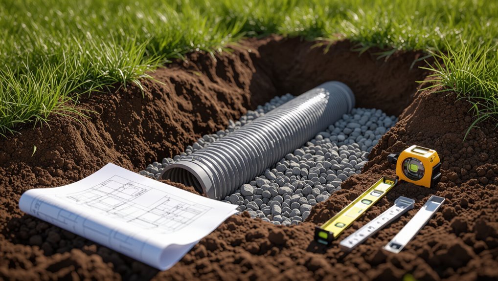
A septic drain field is the component that receives and disperses clarified effluent from the septic tank into surrounding soil, where biological and physical processes further treat the wastewater.
Proper design guarantees the tank effluent is evenly distributed, the soil has adequate absorption and treatment capacity, and system components are sized and sited to prevent hydraulic overload or groundwater contamination.
Poor design or installation commonly leads to surface pooling, clogging, sewage backups, and premature system failure.
Purpose and function of a drain field
Septic drain fields perform the critical task of returning treated wastewater to the soil while preventing contamination of groundwater and surface water.
They distribute effluent evenly, enable biological treatment in the soil, and protect public health. Proper sizing, layout, and materials guarantee longevity and avoid failures.
Readers asking how do you build a septic drain field must follow codes, site evaluation, and quality installation.
How a drain field interacts with the septic tank and soil
Connects the tank and the surrounding soil, the drain field receives clarified effluent from the septic tank and disperses it through a network of pipes or trenches where soil microorganisms complete treatment.
Gravity or pumps control flow; distribution promotes even percolation.
Soil texture, depth, and permeability determine absorption and pathogen removal rates.
Proper separation from groundwater prevents contamination and preserves long-term function.
Common failures from poor design or installation
Poor design or improper installation commonly leads to drain field failures that manifest as slow drains, surface pooling, odors, and eventual system overload.
Common causes include incorrect trench depth, insufficient soil percolation testing, improper pipe slope, compacted or contaminated soil, inadequate pipe spacing, and using undersized or unsuitable aggregate.
These defects accelerate clogging, reduce treatment capacity, and necessitate costly repairs or replacement.
Codes, Permits, and Site Evaluation Requirements
Before breaking ground, the author outlines the typical permitting process and necessary documentation required by local health or building departments.
Key code considerations—such as setbacks, trench depth, approved materials, and when a licensed professional is required—shape design decisions, while soil testing and perc test procedures determine site suitability and allowable system types.
A clear summary of when to hire a professional versus pursuing limited DIY work helps readers comply with regulations and avoid costly mistakes.
Typical permitting process and required documentation
Permitting for a septic drain field requires adherence to local, state, and sometimes federal regulations, and begins with obtaining the correct codes and permits and completing a site evaluation that documents soil conditions, setbacks, and system design.
Applicants submit permit applications, engineered plans, soil report, site map, homeowner or contractor contact info, and fees.
Review, inspection scheduling, and permit issuance follow upon compliance.
Key local and national code considerations (setbacks, depth, materials)
After obtaining permits and completing the site evaluation, attention turns to the specific code requirements that dictate drain field layout and construction.
Local and national codes prescribe setbacks from wells, property lines and water bodies, minimum and maximum trench depths, soil treatment zones, approved pipe and aggregate materials, inspection access, and surface cover.
Compliance guarantees health, longevity, and permit approval.
When to hire a licensed professional vs. DIY
When is a homeowner expected to call a licensed professional rather than attempt a do‑it‑yourself drain field?
Complex permits, local code interpretations, proximity to water sources, high groundwater, steep slopes, or systems serving multiple units typically require licensed designers or installers.
Professionals handle permit applications, inspections, engineered designs, and liability concerns.
Simple, code‑clear single‑family installations with compliant site conditions may be DIY if allowed.
Soil testing and perc test procedures and interpretation
Soil testing—especially percolation (perc) tests—determines whether a site can support a septic drain field and what design provisions are required under local codes.
Technicians dig test pits, evaluate texture, depth to seasonal high water, and mottling, then perform timed perc tests.
Results classify soil absorption rates, dictating trench length, bed sizing, and required setbacks.
Permit approval depends on compliant documentation.
Planning the Drain Field: Sizing and Layout
The planner begins by calculating the daily wastewater load and design flow to determine required absorption area.
Soil perc rates and sizing charts are then used to translate flow into trench, bed, or mound dimensions.
Layout options are compared for single-family and multi-bedroom systems to match system type, property constraints, and regulatory setbacks.
Calculating daily wastewater load and design flow
Although accurate sizing depends on local codes and household habits, calculating daily wastewater load and design flow begins with estimating the predictable volume produced by occupants and fixtures.
The designer multiplies fixture unit values or per‑person gallons per day by occupancy, adds intermittent loads (guests, irrigation returns), applies safety and peak factors, then determines required trench length and distribution capacity for compliant system performance.
Soil absorption rates and sizing charts
After establishing design flow, attention shifts to percolation characteristics and absorption capacity of the native soils, which determine trench length, spacing, and overall field footprint.
Perc rates (minutes per inch) and soil texture guide allowable loading rates. Standard sizing charts translate percolation results into linear feet per bedroom or gallon-per-day.
Adjustments account for limiting layers, seasonal high water table, and local code safety factors.
Choosing between trench, bed, and mound systems
Several factors determine whether a trench, bed, or mound system is appropriate for a given site: soil percolation rate, depth to limiting layers or seasonal high water table, available area, and expected sewage loading.
Trench systems suit deep, well-drained soils with limited area.
Bed systems require more area and uniform soils.
Mound systems are for high water tables, shallow soils, or poor percolation, providing engineered fill and distribution.
Layout examples for single-family and multi-bedroom systems
A clear layout translates household wastewater needs into trench lengths, bed areas, or mound footprints by matching the system type to expected daily flow and percolation characteristics.
Examples contrast single-family 3‑bedroom footprints with larger multi-bedroom demands, showing modular expansion, parallel trenches, or increased bed area.
Typical guidelines:
- Single-family: compact trenches sized to 300–600 GPD percolation.
- Multi-bedroom: parallel arrays, staged capacity.
- Mound: footprint scales with loading.
Materials and Equipment Needed
The section catalogs essential materials and equipment for constructing a drain field, including suitable pipe types, aggregate, geotextile fabric, and distribution media.
It also covers septic tank interface components and risers to guarantee proper connections and access.
Finally, required tools and machinery for excavation and installation are outlined to match project scale and site conditions.
Pipe types, aggregate, geotextile fabric, and distribution media
Durable, properly sized components are essential for a septic drain field to function reliably. Pipe selection, aggregate quality, geotextile fabric, and distribution media must match soil conditions and system design specifications.
Use perforated PVC or polyethylene distribution pipe, clean washed gravel or uniform aggregate, nonwoven geotextile to prevent clogging, and appropriate chambers, rockless trenches, or leaching modules sized per hydraulic load.
Septic tank interface components and risers
Septic tank interface components and risers form the essential connection between the septic tank and the drain field, controlling access, flow, and maintenance.
Required materials include watertight lids, ASTM-rated riser sections, inlet/outlet tees or baffles, inspection ports, gaskets, and secure fasteners.
Components must match tank material, resist corrosion, provide airtight seals, and permit easy inspection, pumping, and future modifications.
Tools and machinery for excavation and installation
Begin by assembling a concise set of tools and heavy equipment matched to site conditions and project scale.
Essential items include compact excavator or backhoe, trencher, and skid-steer for earthwork; hand tools for grading and inspection; lifting gear for pipes and chambers.
Prioritize safety gear and calibration tools.
- Heavy equipment
- Hand tools and lifting gear
- Safety and measuring instruments
Step-by-Step Installation Process
The installation sequence begins with pre-construction safety checks and site preparation to guarantee proper access, grading, and utility locates.
Excavation follows, with trenches cut to specific depth, width, and slope before distribution pipes and inlet connections are laid.
Aggregate, geotextile, and backfill are then installed and capped, and inspection ports, cleanouts, and access risers are fitted for future maintenance.
Pre-construction safety and site preparation
Survey the site and secure necessary permits before any excavation begins, ensuring local regulations and setback requirements are met and documented.
Identify utilities, mark protected trees, and establish erosion control.
Create a safety plan covering equipment operation, trench shoring, confined-space protocols, and PPE requirements.
Communicate roles, emergency procedures, and access routes to all personnel.
Stabilize surfaces and install sediment barriers before work starts.
Excavation: depth, width, and slope guidelines
With permits verified and the site secured, excavation proceeds according to the approved plan and safety protocols.
Trenches are dug to specified depth so laterals sit below frost line and above restrictive layers. Width accommodates bedding and inspection access; slope is uniform (typically 1–2% unless code dictates otherwise) to guarantee proper effluent distribution and prevent ponding.
Spoil is stored clear of trench edges.
Installing distribution pipes and inlet connections
Begin by laying out the distribution layout against the excavation plan, confirming invert elevations and outlet positions before any pipe is placed.
Install perforated or slotted distribution pipes on grade, maintaining specified slope and alignment. Use approved fittings and solvent or gasketed joints per code.
Connect inlet piping from the tank with proper drop and access for cleanouts. Secure and support pipes to prevent movement.
Aggregate placement, geotextile wrapping, and backfill
Place clean, washed aggregate evenly over the distribution pipes to the specified depth, ensuring the material is free of fines and meets gradation requirements.
Compact gently to stabilize pipes without crushing.
Lay geotextile fabric over aggregate, overlapping seams per manufacturer, securing edges to prevent intrusion.
Backfill with native soil in lifts, avoiding heavy equipment directly over trenches, and restore grade for drainage and vegetation establishment.
Installing inspection ports, cleanouts, and access risers
Install inspection ports, cleanouts, and access risers so they provide durable, watertight, and readily accessible entry points to the distribution network for inspection, maintenance, and future repairs.
Position risers over inspection chambers and lateral termini, level and plumb. Use solvent-welded or gasketed fittings, secure lids to prevent infiltration, and seal joints.
Label access points and verify alignment with distribution boxes.
Final grading, landscaping, and surface restoration
With inspection risers, cleanouts, and access points secured and labeled, attention shifts to restoring the surface and final grading to guarantee proper drainage, protect the drain field, and provide an aesthetic finish.
Soil is compacted lightly, slopes shaped for runoff away from the field, topsoil spread, and erosion control installed.
Plantings use shallow‑rooted grasses; trees and heavy landscaping remain clear of the area.
Testing, Inspection, and Commissioning
A final inspection verifies that the drain field meets all local code requirements using a concise checklist covering trench depths, aggregate placement, pipe slopes, and setback distances.
Hydraulic loading and soakage tests confirm the system’s percolation capacity and distribution uniformity under expected flows.
Complete documentation of test results, inspection findings, and as-built drawings is compiled for permit closeout and long-term maintenance records.
Inspection checklist for code compliance
Several critical items must be verified during inspection to confirm a septic drain field meets code requirements for testing, inspection, and commissioning.
Inspectors should confirm permitted design matches installation, trench depth and separation distances, soil cover and compaction, pipe gradient and integrity, access risers and markers, proper backfill materials, erosion controls, inlet/outlet sealing, and documentation of as-built plans, materials, and installer certifications for regulatory approval.
Hydraulic loading tests and soakage checks
Initiate hydraulic loading tests and soakage checks to verify that the drain field accepts and disperses effluent at the design rate without ponding or lateral migration.
Measure infiltration rates, apply incremental volumes matching design load, and monitor water level recovery times.
Record soakage uniformity across trenches, identify preferential flow or saturation zones, and require corrective actions—adjust trench spacing, replace media, or improve distribution—to meet performance criteria.
Documenting installation for permit closeout
Complete documentation of the drain field installation is required for permit closeout and must demonstrate that testing, inspection, and commissioning were performed in accordance with approved plans and local regulations.
Records should include as-built drawings, material certifications, compaction and permeability test results, inspection reports, photographed milestones, contractor and inspector signatures, and operation/maintenance instructions.
Submit organized packets to the authority for final approval and retention.
Operation, Maintenance, and Longevity
A clear routine maintenance schedule—regular pumping and periodic inspections—is essential to preserve drain field function and identify problems early.
Owners should follow best practices such as conserving water, diverting roof and footing drains away from the field, and avoiding heavy loads or impervious cover.
Recognizing signs of failure (soft or wet areas, sewage odors, slow drains) and acting promptly, along with understanding typical lifespan and factors like soil, loading, and maintenance, will maximize longevity.
Routine maintenance schedule (pumping frequency, inspections)
Establishing a routine maintenance schedule assures the septic system operates reliably and prevents costly failures; pumping frequency and regular inspections form the core of that routine.
Owners should arrange pumping every 3–5 years depending on household size and tank capacity.
Annual inspections verify scum and sludge levels, distribution box function, and drainfield saturation.
Prompt repairs and recordkeeping extend system life and assure code compliance.
Best practices to protect the drain field (water conservation, routing roof drains)
When protected through mindful household habits and proper site management, a drain field can function efficiently for decades; conserving water, directing roof and foundation runoff away from the leach field, and minimizing vehicle or heavy equipment traffic over the area are central measures.
Additional practices include repairing leaks promptly, installing low-flow fixtures, routing gutter downspouts to stable discharge points, avoiding impermeable paving, and preserving vegetative cover.
Signs of failure and immediate corrective actions
Monitor the drain field for obvious indicators of malfunction: persistently wet or spongy ground, foul odors, slow-draining toilets and fixtures, sewage surfacing or pooling, and unusually green or lush vegetation over the leach area.
Upon noticing signs, stop water-intensive activities, contact a licensed septic professional, inspect the tank and lines, pump the tank if full, and fence off saturated areas to prevent compaction or exposure.
Typical lifespan and factors affecting durability
Although properly designed and maintained drain fields can function for decades, their typical lifespan usually ranges from 20 to 40 years.
Longevity depends on soil permeability, hydraulic loading, maintenance frequency, household size, septic tank pumping schedule, presence of invasive roots or heavy vehicles, chemical disposal, and design quality.
Proactive inspections and conservative water use extend service life and delay costly replacements.
Common Problems, Causes, and Repair Options
Common drain field failures include clogging, ponding, and surfacing effluent, each requiring prompt diagnosis to identify whether biological, hydraulic, or structural causes are at work.
Tree root intrusion and mechanical damage present distinct challenges and are addressed through targeted removal, protective barriers, or pipe replacement.
Decisions to rehabilitate versus replace a drain field hinge on the extent of contamination, remaining system life, and cost-effectiveness of repairs.
Clogging, ponding, and surfacing effluent: diagnosis and remediation
When a drain field exhibits clogging, ponding, or surfacing effluent, these symptoms indicate impaired soil absorption or system overload that require prompt diagnosis to prevent health hazards and environmental damage.
Inspection should assess solids accumulation, saturated trenches, high groundwater, and hydraulic overloading.
Remediation options include pumping, rest periods, amended media or replacement of affected trenches, improved diversion/drainage, and reducing water use until professional evaluation confirms restoration.
Tree root intrusion and mechanical damage solutions
Problems such as clogging and surfacing effluent can also stem from physical assaults on the drain field: tree roots invading pipes and trenches or mechanical damage from construction equipment that crushes, severs, or compacts the absorption zone.
Solutions include targeted root cutting and chemical root inhibitors, trench excavation and pipe replacement, soil decompaction, protective root barriers, and restricting heavy equipment access to preserve filtration capacity and pipe integrity.
When to rehabilitate vs. replace a drain field
How should a homeowner decide between rehabilitating a failing drain field and installing a new one? Factors include soil saturation, age, extent of biomat, and repair history.
Rehabilitate when issues are localized and soil percolation remains adequate; replace for pervasive failure or regulatory noncompliance.
- Assess: soil tests, inspection, repair history
- Cost: short-term rehab vs. long-term replacement
- Compliance: codes, setbacks, permits
Cost Factors and Budgeting Guide
A concise cost overview breaks expenses into materials, labor, permits, and required testing to set realistic expectations.
Practical strategies for reducing costs without violating codes—such as competitive bidding, phased installations, and selecting durable yet affordable materials—can lower total outlay.
Available financing options and local incentives or rebates should be evaluated early to improve affordability and cash-flow planning.
Typical cost breakdown (materials, labor, permits, testing)
Several cost elements typically determine the total price of installing a septic drain field, including materials, labor, permits, and required testing. Typical breakdown: materials (pipes, aggregate, distribution box), labor (excavation, installation), permits and inspections, and soil/percolation testing. Costs vary by region, system size, and site complexity.
| Category | Typical Cost Range |
|---|---|
| Materials | $1,000–$5,000 |
| Labor/Permits/Testing | $2,000–$8,000 |
Cost-saving strategies without compromising compliance
Having outlined typical cost components—materials, labor, permits, and testing, the discussion now shifts to practical strategies that reduce expenses while maintaining regulatory compliance.
Competitive bidding, phased construction, durable material selection, and accurate site assessment minimize overruns.
Reusing certified components, coordinating inspections, and hiring experienced contractors prevent costly rework.
Prioritize long-term performance rather than lowest initial price to guarantee compliance and lower lifetime costs.
Financing options and incentives
Where can homeowners turn for funding when septic drain field costs exceed savings?
Practical options include state or county grants, low-interest rehabilitation loans, USDA rural development programs, and utility or health-department subsidies.
Tax credits or energy-efficiency incentives may apply for advanced systems.
Home equity lines, contractor payment plans, and nonprofit assistance provide alternatives.
Eligibility, application timelines, and matching requirements vary by program.
Case Examples and Practical Scenarios
The section presents three concise case examples to illustrate common design choices and constraints.
The first covers a standard trench system sized for a three‑bedroom home.
The second describes a mound system for a property with a high water table.
The third outlines an adaptive retrofit approach for a failing drain field.
Each scenario highlights site conditions, key design decisions, and expected performance trade‑offs.
Example 1: Standard trench system for 3’bedroom home
Although soil and site conditions vary, this example outlines a typical standard trench drain field designed to serve a three‑bedroom home, detailing layout, sizing, and common installation steps.
The plan uses multiple 100‑foot trenches spaced 8–10 feet apart, 18–24 inches wide, and 24–36 inches deep with washed stone, pipe with holes, fabric cover, and appropriate slope to guarantee even distribution and percolation.
Example 2: Mound system on high water table site
A property with a high seasonal water table cannot rely on standard trenches, so designers often specify a raised or “mound” system to provide adequate unsaturated soil for effluent treatment.
The mound combines imported sand, pressure-dosed distribution, and graded contours to elevate the treatment zone above groundwater.
Sizing follows soil percolation, loading rates, setback rules, and access for maintenance and inspections.
Example 3: Adaptive retrofit for failing drain field
Addressing a failing drain field often requires an adaptive retrofit that balances site limitations, existing infrastructure, and long-term performance goals.
The example describes diagnosing compaction, root intrusion, and hydraulic overload, then selecting targeted actions: relocating laterals, installing sand/peat polishing, raising trenches with imported fill, or converting to pressure distribution.
Regulatory approval, staged construction, and post-retrofit monitoring guarantee durability and code compliance.
Quick Reference Checklists
A set of concise checklists helps guarantee consistency and compliance throughout the septic drain field project.
Included are pre-installation items for permits and site readiness, post-installation steps for inspection and commissioning, and an annual maintenance list to sustain system performance.
Each checklist targets critical actions and documentation to reduce oversights and simplify handoffs.
Pre-installation permit and site checklist
One clear checklist item set guarantees all permits, site constraints, and preparatory tasks are identified before excavation begins.
The checklist should document regulatory approvals, utility locate confirmations, soil and setback validations, and erosion control plans.
Prioritize documented sign-offs to prevent delays.
- Permits and approvals
- Site assessments and locates
- Preparatory controls and sign-offs
Post-installation inspection and commissioning checklist
Final inspections confirm that the drain field was installed to plan and is ready for safe operation.
A concise commissioning checklist documents compliance, verifies system integrity, and records as-built changes.
Key items include:
- Verify inlet/outlet elevations, trench depths, and media placement match plans.
- Confirm leak-free connections, proper backfill compaction, and distribution uniformity.
- Guarantee permits signed, operator notified, and monitoring ports accessible.
Annual maintenance checklist
Annual inspections keep the drain field functional and prevent costly failures by ensuring components perform as designed and issues are caught early.
A concise annual checklist guides owners and technicians to verify system integrity, operational parameters, and recordkeeping.
- Inspect tanks, filters, lids; measure sludge/scum levels.
- Check distribution box, laterals, and surface for wet spots.
- Document repairs, pump cycles, and schedule next service.
Conclusion
In conclusion, constructing a septic drain field requires thoughtful planning, adherence to codes, and careful execution to guarantee long-lasting, discreet service beneath the landscape. When professionals and homeowners follow sizing, material, and installation guidance, the system continues to perform quietly, avoiding unwelcome surprises. Minor troubles can usually be soothed with timely maintenance or modest repairs, preserving comfort and property value. Prudence, permits, and periodic attention keep the system respectfully out of sight and mind.