How to Measure Flare Fittings Accurately: Step-by-Step Guide for DIYers and Pros
To measure flare fittings accurately, start by identifying the flare type and seat angle. Use calipers to record the outer diameter of the tube and measure the wall thickness to calculate the inner diameter. Next, measure the flare seat and cone geometry, noting the cone height from the machined face. Verify the thread size and pitch with a gauge, and inspect for any damage or deformation. After assembly, confirm that the torque and leak tests are satisfactory. Follow this guide for detailed measurements, tooling tips, and troubleshooting advice.
What Flare Fittings Are and Why Accurate Measurement Matters
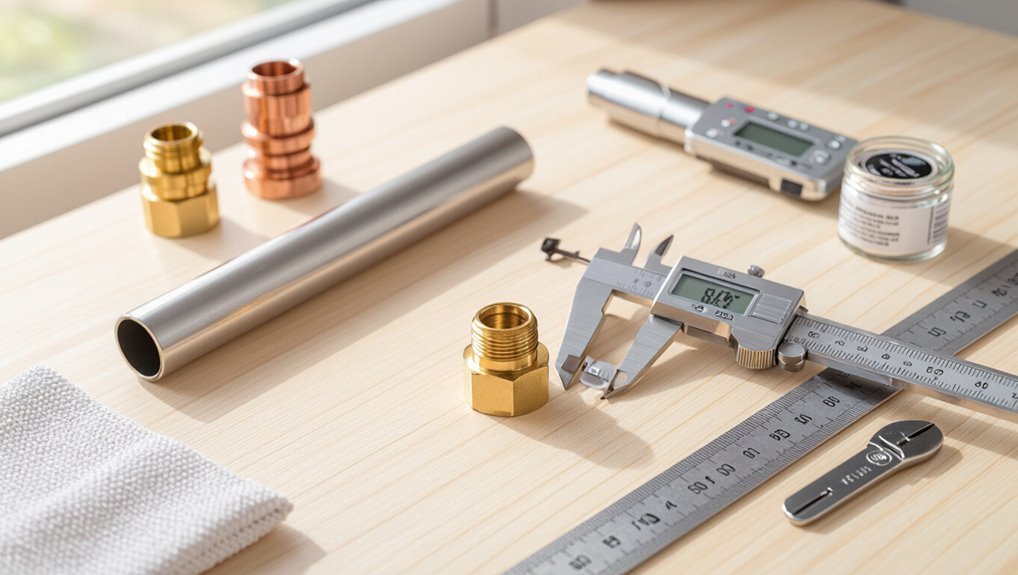
Flare fittings are mechanical connectors with a flared tube end used to join rigid or semi-rigid tubing in fuel, hydraulic, refrigeration, and gas systems.
Accurate measurement guarantees proper seating and sealing of the flare, preventing leaks, pressure loss, and component incompatibility.
Incorrect measurements can lead to dangerous leaks, failed assemblies, and costly downtime or safety incidents.
Definition and common uses of flare fittings
A type of metal connector, flare fittings join tubing by means of a conical flare pressed against a matching seat, creating a leak-resistant seal without solder or adhesives.
Commonly used in refrigeration, fuel lines, brake systems, and HVAC, they suit high-pressure, vibration-prone applications.
Understanding types, materials, and thread standards aids DIYers learning how to measure flare fittings accurately for correct selection and installation.
Consequences of incorrect measurements (leaks, part mismatch, safety)
Having the right flare fitting type, material, and thread standard is only part of the task; precise measurement determines whether a connection performs as designed.
Incorrect measurements cause leaks, reduced pressure, and fluid contamination. Part mismatch leads to stripped threads, repeated replacements, and downtime.
In safety-critical systems, failures risk fire, injury, or environmental harm. Accurate measurement prevents costly repairs and liability.
Quick Answer: How to Measure Flare Fittings in One Sentence
Measure the flare fitting by noting the tube’s outside diameter at the flared end and matching it to the fitting size (e.g., 3/8″ OD), while also confirming thread type and pitch for the mating nut.
Then verify flare style (45° or 37°) and check for any sleeve or ferrule presence to guarantee compatibility, avoiding assumptions based solely on visual similarity.
Tools and Materials Needed for Accurate Measurement
Accurate measurement of flare fittings requires a selection of essential tools: calipers, a straight ruler, thread gauge, and protractor to capture dimensions and angles.
Optional verification tools such as a micrometer, flare nut crowfoot, and templates can improve precision for critical or worn parts.
Proper safety gear and a clean, well-lit workspace guarantee measurements are reliable and components are handled safely.
Essential measuring tools (calipers, ruler, thread gauge, protractor)
A small set of precise tools—digital calipers, a steel ruler, a thread pitch gauge, and a protractor—forms the foundation for reliably measuring flare fittings.
Digital calipers measure outer and inner diameters and shoulder depths; a steel ruler verifies lengths; a thread gauge identifies pitch and engagement; a protractor checks flare angles.
Together they guarantee accurate dimensions for proper fit and leak-free connections.
Optional tools for verification (micrometer, flare nut crowfoot, template)
Confirming flare fitting dimensions often benefits from a few optional verification tools that add precision and confidence to measurements.
A micrometer checks small diameter and lip thickness with high resolution.
A flare nut crowfoot fits over nuts for torque-friendly inspection and alignment.
Templates or reference gauges verify flare angle and seating geometry quickly, reducing assembly errors and confirming caliper or ruler readings.
Safety gear and workspace preparation
Before measuring, the technician assembles appropriate safety gear and prepares a clean, well-lit workspace to protect both the components and the person.
Safety essentials include eye protection, gloves, and hearing protection if cutting or grinding. A stable workbench, good lighting, and magnetic trays prevent loss of small parts.
Clean rags, solvent, and proper disposal for debris guarantee accurate measurements and component integrity.
Types of Flare Fittings and How They Affect Measurement
Different flare standards and materials change how measurements are taken and matched.
The article contrasts 45° and 37° flares by their cone angle and seat shape, explains how metric and SAE/imperial fittings use different thread profiles and sizing, and notes that brass, copper, and stainless variations affect tool choice and sealing behavior.
Readers are guided to identify these features before measuring to guarantee correct fitment.
45° vs 37° flare types and identifying features
Two common flare standards—45° (SAE/JIC) and 37° (AN/JIC for aerospace)—use different cone angles and mating geometries that affect how fittings are measured and identified.
Visual cues include cone angle, flange shape, and nut profile.
37° fittings often have longer, sharper cones and tighter tolerances; 45° fittings display blunter cones and wider seats.
Always confirm with angle gauges or manufacturer specs.
Metric vs SAE/Imperial fittings
Having distinguished 37° and 45° cone geometries and their visual cues, the discussion now moves to how metric and SAE/imperial flare systems differ and influence measurement methods.
Metric fittings use nominal millimeter thread sizes and sometimes unique seat angles; SAE/imperial uses inch-based threads and standard flare dimensions.
Accurate measurement requires identifying thread pitch standard, diameter units, and matching tooling to avoid cross-standard mismatches.
Common materials (brass, copper, stainless) and implications
Because material choice affects both the physical behavior of flare fittings and the tools required to measure them, understanding whether a fitting is brass, copper, or stainless steel is essential before taking measurements.
Brass is softer, resists corrosion, and accepts finer filing; copper is malleable, deforms easily under clamps; stainless is hard, requires sharper calipers and care to avoid burrs.
Adjust technique accordingly.
Step-by-Step Measurement Process for Flare Fittings
A clear procedure guarantees consistent, accurate measurements for flare fittings. The technician should follow a concise sequence of checks and measurements, focusing on angle, diameters, wall thickness, seat and thread details:
- Identify the flare angle and seating surface.
- Measure tube outer diameter (OD).
- Measure tube wall thickness and calculate inner diameter (ID).
- Measure flare seat diameter and cone dimensions (then confirm thread size and pitch for flare nuts).
Step 1 Identify the flare angle and seating surface
Step 1 directs attention to determining the flare angle and whether the fitting seats on the cone or the face, since correct identification is essential for matching mating components and avoiding leaks.
The technician visually inspects and uses a protractor or angle gauge to confirm common angles (37°, 45°).
They also check for conical or flat seating surfaces and note material and thread type for compatibility.
Step 2 Measure tube outer diameter (OD)
Next, the technician measures the tube outer diameter (OD) to determine the correct flare nut and sleeve size.
Using calipers, they measure across the widest exterior point, recording to the nearest 0.01 inch or 0.1 mm. Measurements are taken at multiple spots to check roundness.
The recorded OD is then matched to manufacturer sizing charts to select compatible fittings.
Step 3 Measure tube wall thickness and calculate inner diameter (ID)
Measure the tube wall thickness with precise instruments so the inner diameter (ID) can be accurately calculated for proper flare fitting selection.
The technician records wall thickness using calipers or a micrometer at multiple points to account for variations.
Subtract twice the wall thickness from the measured outer diameter to obtain ID.
Verify consistency and round to required tolerance before choosing compatible fittings.
Step 4 Measure flare seat diameter and cone dimensions
With the tubing prepared, the technician inspects and records the flare seat diameter and cone geometry to guarantee a proper metal-to-metal seal.
Using calipers and a small profile gauge, they measure seat diameter, cone angle, and cone height from the machined face. Measurements are documented to match mating fittings or select correct adapters, ensuring alignment and avoiding leaks without altering thread specifications.
Step 5 Measure thread size and pitch for flare nuts
Identify and record the thread size and pitch of the flare nut to guarantee compatible engagement with mating connectors.
Using a thread gauge, match threads per inch (TPI) or metric pitch; note major diameter with calipers.
Confirm right- or left-hand thread.
Record standard designation (e.g., 1/4″-28, M6×1.0) and tolerance if required for precise replacement or ordering.
Step 6 Verify hex/flange sizes and nut flats
Next, inspect the flare nut’s hex and flange features to determine the correct wrenching dimensions and seating surfaces.
Measure across flats on the hex with calipers for wrench size, note any chamfers or rounded flats, and measure flange diameter and thickness where it mates.
Record flat locations and any irregularities that affect torque or sealing to guarantee proper tool fit and engagement.
Step 7 Record measurements and match to standard sizes
Consolidate all collected dimensions into a single reference sheet and compare each measurement against published flare-fitting standards (AN, SAE, BSP, metric) to determine the correct size and series.
Note inner/outer diameters, thread pitch, flare angle, hex flats and length. Cross-check tolerances and unit systems, record matched standard part numbers, and flag ambiguous or out-of-spec readings for re-measurement or expert review.
How to Use Calipers and Thread Gauges Correctly
The correct use of calipers and thread gauges guarantees accurate OD, ID, and depth readings essential for matching flare fittings.
Caliper best practices include using the proper jaws, zeroing before measuring, and taking multiple measurements for consistency, while thread pitch gauges identify flare nut thread form and pitch.
Common mistakes to avoid are measuring at an angle, applying inconsistent pressure, and misreading worn or damaged gauge teeth.
Caliper best practices for OD, ID, and depth
Begin by selecting a calibrated set of vernier or digital calipers and confirming zero accuracy before use; this guarantees reliable readings for outer diameter (OD), inner diameter (ID), and depth measurements.
Use constant light pressure, seat jaws squarely, and rotate round parts to find maximum OD.
For ID measure with inside jaws at multiple points.
Use depth rod from a stable reference and record to proper resolution.
Using thread pitch gauges for flare nut threads
After confirming caliper accuracy and obtaining reliable OD, ID, and depth readings, attention turns to verifying flare nut thread form and pitch with a thread pitch gauge and calipers used in tandem.
The technician matches gauge teeth to threads, notes pitch (TPI or metric), then measures major diameter with calipers to confirm standard size.
Record both values for correct replacement or pairing.
Common measurement mistakes to avoid
Avoiding common measurement errors requires discipline and the right technique. The user should zero calipers before each use, measure at consistent points, and avoid angled readings.
Thread gauges must seat fully without forcing; damaged leaves invalidate readings. Ignore worn or contaminated tools.
Record measurements immediately and double-check critical dimensions. Consistent technique and tool maintenance prevent misfits and leaks in flare fittings.
Reference Charts and Conversion Tips
A concise set of reference charts and conversion tips helps technicians quickly match SAE/Imperial and metric flare tube sizes and find thread equivalents. The following quick-reference table highlights common tube size equivalents, metric counterparts, and typical thread conversions to consult during measurement. Use these values as starting points and verify against actual fittings before final assembly.
| SAE/Imperial Size | Metric Equivalent | Thread Conversion |
|---|---|---|
| 1/4″ | 6 mm | 7/16″-20 UNF |
| 3/8″ | 10 mm | 9/16″-18 UNF |
Common SAE/Imperial flare tube sizes and equivalents
Reference charts for flare fittings outline the common SAE and imperial tube sizes, show nominal and actual dimensions, and list typical cross-references used in plumbing and hydraulic systems. They list common sizes, thread types, and ANSI/BSP equivalents for troubleshooting and ordering.
| Nominal | Actual OD | Common Equivalent |
|---|---|---|
| 1/8″ | 0.405″ | SAE J512 |
| 3/16″ | 0.500″ | AN/SAE |
| 1/4″ | 0.540″ | 7/16″-20 UNF |
| 3/8″ | 0.675″ | 9/16″-18 UNF |
Common metric flare sizes and equivalents
When working with metric flare fittings, technicians rely on standardized designations (such as 4 mm, 6 mm, and 8 mm) that correspond to tube outer diameters and thread forms like M10x1 or M14x1.5; concise charts translate these nominal sizes into actual outside diameters, flare cone dimensions, and common imperial equivalents to simplify selection and cross-referencing.
| Metric size | OD (mm) | Imperial approx |
|---|---|---|
| 4 mm | 4.0 | 5/32″ |
| 6 mm | 6.0 | 1/4″ |
| 8 mm | 8.0 | 5/16″ |
Thread size conversion quick-reference
Because thread dimensions often differ between metric and imperial systems, a concise conversion quick-reference is essential for matching fittings and avoiding leaks or cross-threading. The chart lists common pairings and pitch to help identify equivalents quickly; verify with calipers or thread gauges before final assembly.
| Metric (mm) | Imperial (in) |
|---|---|
| 4.0 x 0.7 | 1/8″ BSPP |
| 6.0 x 1.0 | 1/4″ NPT |
| 8.0 x 1.25 | 5/16″ UNF |
| 10.0 x1.5 | 3/8″ NPTF |
Matching Measured Dimensions to Replacement Parts
The process of matching measured dimensions to replacement parts begins with interpreting part numbers and application specifications to confirm size, material, and pressure ratings.
Technicians then cross-reference manufacturer charts and industry standards to verify compatibility and identify equivalent items.
If no direct replacement exists, the choice between adapters or custom fittings is made based on sealing method, flow requirements, and service conditions.
How to read part numbers and application specs
Interpreting part numbers and application specifications requires translating measured dimensions into the manufacturer’s coding system so the correct replacement is identified.
The reader compares tube OD, flare angle, thread size, and seat type to code segments. Note pressure ratings, material and temperature limits.
Decode suffixes for fittings, note tolerances, and verify application notes to confirm compatibility before ordering replacements.
Cross-referencing manufacturer charts and standards
One step in matching measured flare dimensions to replacement parts is consulting manufacturer charts and industry standards to translate raw measurements into specific part codes.
The user should compare outer diameter, flare angle, and tube wall thickness against published tables, note material and thread standards (e.g., SAE, JIC), and confirm tolerances to verify direct replacements rather than guesswork.
When to choose adapters or custom fittings
After confirming dimensions against manufacturer charts and standards, a decision must be made whether a direct replacement is feasible or if an adapter or custom fitting is required.
Choose adapters when thread type, flare angle, or material differ but pressure ratings and space allow.
Specify custom fittings for unique geometries, obsolete parts, or incompatible pressures.
Document measurements, materials, and operating conditions for supplier fabrication.
Troubleshooting Measurement Problems
When measurements produce unexpected results, inspection for damaged or deformed flare ends is the first step.
The technician should also check for non-standard or worn threads that can skew caliper and gauge readings.
If no standard size matches the measurements, documenting the anomalies and consulting manufacturer specifications or a specialist is recommended.
Dealing with damaged or deformed flare ends
Inspecting a flare end that is nicked, crushed, or out-of-round requires a methodical approach to salvage accurate measurements.
Assess damage visually and with calipers, rotate the tube to find the least-deformed profile, and record multiple diameter readings.
Light burrs may be dressed with a fine file; severely deformed ends warrant replacement.
Document defects and note potential measurement uncertainty for fittings replacement.
Identifying non-standard or worn threads
Even with a usable flare end, thread condition can undermine a fitting’s fit and seal; attention now shifts to identifying non-standard or worn threads.
Inspect threads for flattened peaks, inconsistent pitch, cross-threading, corrosion, or burrs. Use a thread gauge and magnification to compare profile and spacing.
Document deviations; damaged threads may require rethreading, inserts, or replacement to restore reliable sealing.
When measurements don’t match any standard size
If measurements fail to correspond with standard flare sizes, the technician should treat the discrepancy as a diagnostic cue rather than an endpoint.
Inspect for wear, deformation, or partial threading; remeasure with calibrated calipers at multiple points and verify thread pitch with a gauge.
Consider custom adapters, damaged-seat repair, or consulting manufacturer drawings.
Document findings and label the fitting as nonstandard for future reference.
Common DIY Scenarios and Step-by-Step Examples
The section presents common DIY scenarios with clear, step-by-step measurement examples for typical flare-fitting tasks.
Readers are shown practical approaches for:
- Replacing a brake line flare on cars
- Measuring fittings for refrigeration or AC lines
- Plumbing gas line flare replacement example
- Tools and verification steps to guarantee proper fitment
Each example outlines key measurements, required tools, and safety checks in sequence.
Replacing a brake line flare on cars
Begin by evaluating the damaged section and confirming the flare type, fitting size, and material before attempting replacement; brake lines commonly use double (bubble) flares in steel lines and single flares in softer metals like copper or aluminum.
Use a proper flaring tool, cut and deburr to length, clamp squarely, form the correct flare, inspect for cracks, then pressure-test and bleed the system per manufacturer specifications.
Measuring fittings for refrigeration or AC lines
Several common DIY refrigeration and air-conditioning projects require accurate measurement of flare and flareless fittings to guarantee leak-free connections and correct component replacement.
Technicians measure thread diameter, thread pitch (or use nut diameter for flareless), tube OD, and flare angle (45° common).
Use calipers, thread gauges, and compare fittings to manufacturer specs or service manuals.
Record sizes before ordering replacements.
Plumbing gas line flare replacement example
Many of the same measurement habits used for refrigeration and AC — confirming tube outer diameter, flare angle, and thread details — apply when replacing a gas line flare fitting.
However, gas fittings demand stricter attention to leak testing and local code compliance.
The example outlines verifying tubing size, matching 45° or 37° flare profile, choosing approved materials, torquing per spec, and performing pressure/leak tests with soapy solution or gauge.
Mistakes DIYers Make and How to Avoid Them
The section highlights common measurement and installation errors and how to prevent them.
Typical pitfalls include:
- Relying on visual matching instead of precision tools
- Ignoring flare angle differences
- Over-tightening and causing distortion
- Skipping verification measurements before final assembly
Practical tips that follow will show simple checks and correct techniques to avoid these mistakes.
Relying on visual matching instead of precision tools
Relying on visual matching instead of precision tools often leads to mismatched flare fittings, leaks, or wasted parts.
Estimating by eye ignores minor diameter and seat differences critical for sealing.
Professionals use calipers, gauges, and templates to confirm sizes before cutting or flaring.
DIYers should measure, not guess: verify tubing OD, flare type, and nut fit to prevent rework and failures.
Ignoring flare angle differences
How can a seemingly small angle difference compromise an entire flare joint? Even minor mismatches between male and female flare angles prevent full metal-to-metal contact, causing leaks, vibration, and premature wear.
DIYers should measure angles with a protractor or angle gauge, verify standards (45° vs 37°), and replace mismatched fittings rather than forcing assemblies that won’t seal reliably.
Over-tightening and causing distortion
Over-tightening flare fittings can deform the flare lip or compress the tubing, turning a simple seal into a leak-prone joint.
Excess torque distorts seating surfaces, damages flare shape, and stresses fittings. Use manufacturer torque specs, calibrated tools, and finger-tight plus quarter-turn methods where applicable.
Inspect flares for distortion and replace damaged components; proper torque preserves seal integrity and prevents leaks.
Maintenance, Verification, and Final Assembly Checks
After measurement and installation, attention turns to maintenance, verification, and final assembly checks.
Recommended procedures include leak-testing methods, confirming torque specifications and tightening sequence, and establishing a schedule for periodic inspections.
These steps guarantee fittings remain secure and leak-free throughout service.
Leak-testing methods after installation
Verify flare fittings for leaks using systematic, documented methods to guarantee integrity before placing a system into service.
Perform pressurized tests with inert gas or air and a calibrated gauge, monitor for pressure decay, and apply approved soapy solution or electronic leak detector along joints.
Record test conditions, duration, and results.
Isolate sections to pinpoint defects and repair or retest until criteria are met.
Torque specs and proper tightening sequence
Establish and follow specified torque values and a controlled tightening sequence to secure flare fittings. Achieve proper preload without damaging tubing or threads.
Use calibrated torque wrenches, apply gradual incremental turns in the recommended pattern, and torque to manufacturer specifications.
Verify wrench accuracy, avoid overtightening, and make sure opposing nuts or adapters are held to prevent twisting.
Record final torque and assembly order for verification.
Periodic inspection tips
Routine inspections guarantee flare fittings remain leak-free and mechanically sound throughout service life.
Inspect visually for corrosion, cracks, or deformation; verify flare lip integrity and nut seating.
Check torque against specifications and look for fluid residue or dye indicating leaks.
Perform pressure or soap-bubble tests after reassembly.
Record findings, replace damaged components, and schedule follow-ups based on operating conditions and manufacturer guidance.
When to Call a Professional and Sourcing Parts
If measurement or repair requires specialized tools, pressure certification, or safety training, a professional should be contacted.
When ordering parts, provide the exact flare angle, tubing OD, wall thickness, and material to the supplier to guarantee compatibility.
Prefer OEM parts for critical systems, but reputable aftermarket vendors can be acceptable if they match specifications and offer traceability.
Situations requiring specialized tools or certification
Many complex flare-fitting tasks require more than a basic wrench and tape measure, particularly when work involves pressurized systems, gas lines, or vehicle fuel lines where a poor seal could cause leaks, fire, or regulatory violations.
Specialized tools (flare nut wrenches, tubing benders, calibration gauges) and certifications (gas, automotive, HVAC) are required for safety, code compliance, and warranty preservation; hire qualified technicians.
How to provide accurate measurements to a supplier
Measure carefully and document each dimension before contacting a supplier: note tube outer diameter, wall thickness or nominal tube size, flare type (45° or 37°), thread size and pitch, and the length from the flare face to any bend or connection.
Provide measurement units, photos with scale, material specification, and application pressure/temp.
If uncertain, record tolerances and ask supplier for verification or recommended fitment.
Recommended vendors and OEM vs aftermarket considerations
Sourcing flare fittings requires balancing reliability, compatibility, and cost: OEM parts offer guaranteed fit and material traceability for critical systems, while reputable aftermarket vendors can provide wider selection and lower prices for non-critical or hard-to-find items.
Buyers should verify specifications, material grades, and thread standards, check vendor reviews, request datasheets, and consider professional installation for safety-critical or high-pressure applications.
Quick Measurement Checklist for DIYers
A simple checklist helps DIYers confirm the four key dimensions and fit details before cutting or ordering flare fittings.
It guarantees accuracy, prevents waste, and speeds installation.
Follow these concise checks:
- Measure tube OD precisely.
- Verify flare angle and type.
- Check nut thread size and pitch.
- Confirm seating depth and wall thickness.
Conclusion
Accurate flare fitting measurement prevents leaks and costly rework. A DIY mechanic once replaced brake lines on a 1998 pickup, misidentifying a 45° SAE flare as inverted and ordering wrong fittings; remeasurements using calipers and the steps above solved the issue, saving hours and expense. When measurements are precise and checks performed, installations seal reliably; professionals should be consulted for complex systems or uncertain measurements to guarantee safety and compliance.