How to Test a Ball Valve: Step-by-Step Guide for Leak, Operation, and Pressure Checks
To effectively test a ball valve, follow these essential steps: First, isolate and depressurize the line. Conduct a visual inspection and operate the handle or actuator to ensure smooth quarter-turn action and minimal stem play. Perform low-pressure seat and body leak tests using water or air, applying gauges and bubble or electronic detectors. If needed, progress to controlled high-pressure testing. Additionally, inspect packing, seats, and the body for any wear, and repair or replace seals as necessary. Finally, document all results for reference. For more detailed procedures and acceptance criteria, continue reviewing the guidelines.
What a Ball Valve Is and When to Test It
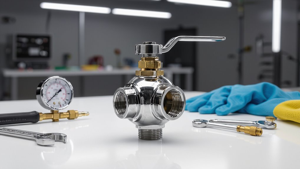
A ball valve is a quarter-turn valve that uses a spherical closure to control flow and is commonly used in plumbing, HVAC, and industrial piping.
Testing is warranted when leaks, stiff operation, loss of pressure, or visible corrosion appear.
Before testing, personnel should follow lockout/tagout procedures and wear appropriate PPE such as gloves, eye protection, and any required respiratory or chemical-resistant gear.
Definition and common applications
Ball valves are quarter-turn shutoff devices that use a hollow, rotating sphere to control flow; their simple mechanism provides fast, tight shutoff and low pressure drop.
Used in water, gas, HVAC, chemical, and industrial systems, they suit isolation, emergency shutoff, and flow control.
Maintenance routines include how to test a ball valve for leaks, operation smoothness, and pressure integrity.
Signs a ball valve needs testing
Several clear indicators signal when a ball valve requires testing: persistent leaks around the stem or body, difficulty turning the handle or incomplete quarter-turn rotation, unexpected pressure drops downstream, and visible corrosion or buildup on internal components.
Additional signs include intermittent flow, noisy operation, seal swelling or cracking, and frequent actuator faults.
Routine testing follows after operational anomalies, age-related wear, or post-repair reassembly.
Safety considerations and required PPE
Personal protective equipment and strict safety procedures are essential before testing a ball valve to protect personnel from pressurized fluid release, chemical exposure, burns, and mechanical hazards.
Required PPE includes safety glasses or face shield, chemical-resistant gloves, flame-resistant clothing, and hearing protection.
Lockout-tagout, depressurization, ventilation, and emergency shutdown plans must be verified.
Only trained personnel should perform tests with appropriate permits.
Tools and Materials Needed for Testing
A concise list of tools and materials sets the foundation for safe, effective ball valve testing.
Essential items include basic hand tools and consumables, pressure testing equipment and leak detection tools, plus personal protective equipment and isolation gear.
Technicians should also prepare common replacement parts and appropriate sealants before beginning work.
Basic hand tools and consumables
Gathering the correct hand tools and consumables streamlines ball valve testing and reduces errors during inspection and minor repairs.
Essential items include adjustable wrenches, hex keys, screwdrivers, pipe wrenches, pliers, and torque wrench.
Consumables: thread sealant, PTFE tape, replacement gaskets/O-rings, cleaning solvent, shop rags, and disposable gloves.
Keep a small parts tray and basic flashlight for organized, safe work.
Pressure testing equipment and leak detection tools
Pressure testing equipment and leak detection tools are critical for verifying ball valve integrity under expected service conditions and for pinpointing faults without disassembly.
Common items include calibrated pressure gauges, hydrostatic or pneumatic test pumps, deadweight testers, and pressure regulators.
Leak detection uses soap solution, ultrasonic detectors, tracer gas (helium) kits, and electronic sniffers.
Selection depends on system pressure, media, sensitivity, and access constraints.
Recommended personal protective equipment and isolation gear
Before testing begins, personnel should be equipped with appropriate personal protective equipment (PPE) and isolation gear tailored to the valve’s service conditions and potential failure modes.
Required items include chemical-resistant gloves, safety glasses or face shield, hearing protection, flame-resistant clothing when applicable, and safety boots.
Isolation gear: lockout/tagout kits, blind flanges or double block-and-bleed assemblies, pressure-rated blinds, and venting lines.
Preparing replacement parts and sealants
With isolation secured and PPE in place, the technician verifies that spare components and sealants match the valve’s specifications and the service media.
The kit includes correct ball, seats, stem seals, O-rings, gland packing, and compatible thread sealant or PTFE tape.
Parts are inspected for damage, batch codes noted, and a torque-rated wrench and lubricant are staged for prompt, correct replacement.
Preparing the Valve and System for Testing
Before testing, the valve must be isolated from the system and any upstream or downstream sources secured.
The procedure requires depressurizing and draining the line, followed by cleaning and a visual inspection to identify damage, debris, or corrosion.
The technician records the valve’s condition and orientation, including any markings or anomalies, before proceeding.
Isolating the valve from the system
Isolating the ball valve from the system requires shutting off upstream and downstream sources, depressurizing the line, and verifying zero energy before any inspection or test begins.
The tester secures lockout/tagout, confirms adjacent valves are closed, and uses blinds or spool removal if required.
Electrical and mechanical hazards are checked; permits and notifications are completed.
Isolation is documented before proceeding.
Depressurizing and draining procedures
Having secured isolation and verified zero energy, the next step is to depressurize and drain the valve and adjacent piping to remove trapped fluid and residual pressure.
Open designated vents and drain points, follow bleed-down procedures, and monitor pressure gauges until stable zero.
Collect and dispose of drained fluid per procedure.
Confirm vents are closed and caps reinstalled before proceeding to subsequent test preparations.
Cleaning and visual inspection before tests
One thorough cleaning and visual inspection prepares the ball valve and surrounding piping for safe and reliable testing.
Remove debris, corrosion, and residue from bonnet, stem, body, and flanges.
Inspect for cracks, seal damage, loose fasteners, and proper gasket seating.
Verify valve handle movement is unobstructed.
Confirm external surfaces are dry and markings legible before proceeding with operational and leak tests.
Documenting valve condition and orientation
Before testing begins, record the valve’s current condition and orientation in clear, dated notes or photographs to establish a baseline for comparisons and traceability.
Note handle position (open/closed/intermediate), body markings, tag numbers, visible wear, seal condition, and pipeline flow direction.
Include reference measurements, ambient conditions, and tester identity.
Store records with the test protocol for future verification and trend analysis.
Visual and Manual Operation Check
A visual and manual operation check begins with inspecting external components and the actuator for damage, corrosion, or leaks.
The valve should then be manually cycled while observing actuation smoothness, alignment, and any unusual resistance or binding.
Finally, the inspector verifies stem packing integrity, minimal handle play, and that the actuator responds correctly throughout the full travel.
Inspecting external components and actuator
Visually examine the valve body, stem, handle or actuator housing, and adjacent fittings for damage, corrosion, leaks, misalignment, missing fasteners, or foreign debris.
Note actuator mounting integrity, electrical or pneumatic connections, and conduit seals.
Check stem packing and gland for seepage and sealant condition.
Verify nameplate data and orientation markings are legible.
Record any abnormalities for corrective action.
Manually cycling the valve: method and what to observe
Cycle the valve slowly through its full travel by operating the handle or actuator controls while observing and feeling for smooth movement, consistent stops, and defined detents.
Note resistance, binding, grinding, or uneven torque. Watch for visible leaks at joints or body.
Confirm ball seats uniformly against seals at closed position and that flow aligns promptly when opened.
Record anomalies for maintenance.
Checking stem packing, handle play, and actuator response
Inspect the stem packing area, handle play, and actuator response by looking for seepage, wear, and looseness while manipulating the control.
Observe for oil, drips, or crystalline deposits at the stem. Check handle snugness and end play; note binding or excess free play.
Cycle the actuator through full travel, confirm consistent stops, smooth motion, and correct feedback from position indicators.
Low-Pressure Leak Test Procedure (Seat and Body Leak)
The procedure begins with a step-by-step setup for a low-pressure hydrostatic or pneumatic test, including isolation, proper fittings, and instrumentation placement.
The tester then applies pressure incrementally and monitors for safe limits while following protocols to prevent overpressurization.
Any leaks are recorded with location, rate, and conditions, and results are compared to defined acceptance criteria to identify failures.
Step-by-step setup for a hydrostatic or pneumatic low-pressure test
Prepare the test area and equipment methodically before initiating a hydrostatic or pneumatic low-pressure leak test to guarantee accurate seat and body leak assessment.
The technician then follows a concise setup:
- Isolate valve and drain connected lines
- Mount test plugs or caps securely
- Fit pressure gauge and vent/drain connections
- Use appropriate test medium (water/air)
- Verify fittings and visual inspection readiness
How to apply test pressure safely
Before applying pressure, the technician confirms all isolation points, vents, and drains are secure and that gauges and relief devices are correctly rated and calibrated for the selected test medium.
Pressure is increased slowly in controlled increments, holding at each step to monitor stability. Safety zones are maintained, personnel are clear, and test duration and final pressure are recorded before completing the low-pressure leak test.
Detecting and documenting leaks during low-pressure test
Begin visual and tactile inspections immediately after achieving the planned low-pressure hold to detect seat and body leaks.
Inspect joints, stem packing, body bolts, and flange faces for dampness, drips, or bubbles. Use leak detection fluid and clean cloths; gently operate the valve to provoke seepage.
Record leak location, size, test pressure, duration, and corrective actions in the test log.
Acceptance criteria and indicators of failure
When evaluating low-pressure seat and body leak tests, acceptance is based on defined thresholds for visible seepage, pressure decay, and operational performance over the specified hold time.
Acceptance requires no observable liquid droplets, pressure loss within allowable limits (e.g., ≤X% or specified psi), and smooth cycle operation without binding.
Failure includes dripping, excessive decay, or impaired actuation, prompting repair or replacement.
High-Pressure and Service-Condition Pressure Testing
High-pressure and service-condition pressure testing is performed after initial low-pressure checks or when valves are specified for elevated operating pressures to verify integrity under realistic loads.
The procedure outlines step-by-step pressurization, required safety checks, observation points for deformation, seat failure, and external leaks, and defined hold times with pass/fail thresholds.
Test operators must monitor pressure stability and physical condition throughout the hold period and record results against the acceptance criteria.
When to perform high-pressure testing
Why perform high-pressure and service-condition pressure testing at specific stages of a ball valve’s lifecycle?
Testing is scheduled after manufacture, post-installation, following major repairs, and before commissioning to verify integrity under expected and extreme pressures.
Periodic testing during service addresses aging, thermal cycling, and material degradation.
Tests also follow changes in service conditions, such as pressure class upgrades or fluid type changes.
Step-by-step high-pressure test procedure and safety checks
Following confirmation of the need and timing for testing, a clear, ordered procedure and safety checklist guide execution of high-pressure and service-condition pressure tests.
Steps include controlled pressurization, hold times, and documented results.
Essential safety checks and actions:
- Verify rated pressure and valve condition
- Isolate and vent adjacent systems
- Use pressure gauges and relief devices
- Apply incremental pressure steps
- Record readings and inspect connections
Monitoring for deformation, seat failure, and external leaks
Inspectors should continuously monitor the valve body, stem, seats, and external seals during pressurization for any signs of deformation, seat displacement, or fluid egress.
Visual inspections, tactile checks, and targeted leak detection (soap solution, ultrasonic) identify seat extrusion, stem packing failure, or body bulging.
Immediate depressurization and isolation are required if deformation, persistent weepage, or progressive leakage appears to prevent catastrophic failure.
Pressure hold time and pass/fail thresholds
When conducting both high-pressure and service-condition pressure tests, the specified hold time and clearly defined pass/fail thresholds determine whether a ball valve meets integrity and performance requirements. The hold period allows detection of slow leaks, material creep, and seat relaxation while thresholds quantify acceptable leakage and deformation for the valve class.
Test protocols specify duration, pressure decay limits, allowable seepage rates, and acceptance criteria for deformation and seating integrity.
Leak Detection Methods and Tools
Common leak detection approaches for ball valves include simple soap-solution bubble tests, electronic gas detectors and ultrasonic instruments, and tracer techniques such as dye penetration or tracer gas.
Each method offers trade-offs in sensitivity, speed, cost, and applicability to different fluids and pressure conditions. A practical testing strategy weighs those pros and cons to select the most reliable and feasible option for the valve and service environment.
Soap solution and bubble test technique
Apply a mild soapy solution to the valve joints and stem area to reveal escaping gas or air by forming bubbles at leak points.
Observe slowly while pressurizing the line; persistent bubbles indicate leakage.
Mark and isolate suspected leaks, depressurize before repairs, and rinse residue after testing.
Use non-corrosive soap, avoid open flames, and document bubble size and location for verification and maintenance records.
Electronic gas leak detectors and ultrasonic methods
Combine electronic gas detectors and ultrasonic leak detectors to locate and quantify leaks without directly contacting the joint.
Electronic units identify hydrocarbon or combustible gas concentration, providing ppm readings and alarm thresholds.
Ultrasonic devices detect turbulent noise from high-pressure leaks, useful for inert or non-detectable gases.
Both methods speed inspection, reduce false positives, and document leak severity for repair prioritization and safety compliance.
Dye penetration and tracer gas tests
When visual confirmation is required for small or complex leak paths, dye penetration and tracer gas tests offer complementary approaches for detecting and characterizing leaks without intrusive disassembly.
Dye methods introduce colored or fluorescent fluids into the system and inspect surfaces under visible or UV light.
Tracer gas testing uses helium or hydrogen mixtures with sensitive sniffers to locate and quantify leaks through seals, joints, and valve seats.
Pros and cons of each method
Although each leak-detection method targets the same problem, their advantages and limitations differ markedly in sensitivity, speed, cost, and suitability for specific valve geometries and media. A concise comparison guides selection: dye is simple but less sensitive; tracer gas is sensitive but costly; pressure decay is fast yet may miss intermittent leaks.
| Method | Strength | Limitation |
|---|---|---|
| Dye | Low cost | Low sensitivity |
| Tracer gas | High sensitivity | Higher cost |
| Pressure decay | Fast | Misses intermittent leaks |
Testing Actuated Ball Valves
Testing actuated ball valves begins with verifying actuator alignment and calibration to guarantee the valve reaches true open and closed positions.
Functional tests of electrical and pneumatic actuators should confirm reliable cycling, response time, and torque or pressure requirements.
Emergency/manual override and position feedback checks complete the assessment by validating safe manual operation and accurate control-system integration.
Verifying actuator alignment and calibration
Before operating an actuated ball valve under pressure, confirm that the actuator shaft and valve stem are precisely aligned and the travel stops and positioner are calibrated to the valve’s open and closed points.
Inspect mechanical couplings, remove backlash, and verify concentricity.
Adjust travel stops, zero and span the positioner, and perform low-pressure stroke checks to guarantee accurate correspondence between command signal and valve position.
Electrical and pneumatic actuator functional tests
Initiate functional tests on electrical and pneumatic actuators by verifying their ability to respond accurately to control signals and to produce smooth, repeatable valve motion across the full travel range.
Check signal inputs, feedback positions, cycle times, and torque/air pressure requirements.
Record position feedback against setpoints, monitor for hysteresis or stiction, confirm successful open/close commands, and log any deviations for corrective action.
Emergency/manual override testing
Verify that actuated ball valves can be reliably operated by their emergency or manual override mechanisms to guarantee safe control during power or control-system failures.
Inspect override hardware, confirm clear access and correct fittings, and verify engagement procedures.
Operate overrides under simulated failure conditions, time actions, check for smooth motion and full stroke, and record any binding, backlash, or inability to secure the valve.
Integrating valve position feedback and control verification
Following successful checks of manual overrides, attention shifts to integrating valve position feedback and confirming control-system responses.
The technician verifies positioner calibration, signal wiring, and feedback sensors (potentiometer, encoder, or switch). Controlled commands are issued to exercise open/close and intermediate positions while monitoring response time, accuracy, and alarms.
Discrepancies prompt calibration, wiring correction, or controller configuration updates before final validation.
Troubleshooting Common Failures
The section outlines typical leak sources and methods to isolate whether seals, fittings, or actuator connections are responsible.
It describes clear symptoms for seat wear, ball surface damage, and stem or packing faults to help pinpoint the failure.
It then contrasts quick remedies (tightening, packing adjustment, seal replacement) with scenarios that require full repair or valve replacement.
Common sources of leaks and how to isolate them
Identify typical leak sources before beginning isolation: stem packing, seat wear, body joints, bonnet gaskets, and connected fittings each present distinct failure modes.
Isolate by depressurizing, closing upstream supply, and draining downstream. Apply dye or soapy solution to locate external leaks.
Tighten or replace packing, retorque joints, and swap gaskets or fittings as identified. Verify isolation before further disassembly or pressure testing.
Symptoms of seat wear, ball damage, and stem issues
After isolating and confirming the source of external leaks, attention shifts to internal components where seat wear, ball damage, and stem issues manifest in distinctive ways.
Indicators include persistent internal leakage when closed (worn or damaged seats), scoring or pitting on the ball causing rough operation and poor sealing, and stem play, stiffness, or packing seepage indicating stem or packing failure requiring inspection.
Quick fixes vs. repair or replacement decisions
Weigh quick fixes against full repair or replacement by matching failure severity to risk, cost, and downtime: superficial problems such as minor packing leaks, light stem stiffness, or debris-caused sticking often respond to lubrication, retightening, or seat cleaning, while deeper issues—severely worn or grooved seats, pitted balls, or bent stems—require component replacement or full valve swap to restore reliable sealing and safe operation.
Small leaks, intermittent sticking, or cosmetic damage justify on-site fixes if inspection confirms intact sealing faces and acceptable pressure ratings; otherwise document findings, isolate the line, and budget for parts or replacement to avoid recurrence and safety risks.
Repair, Maintenance, and Replacement Guidelines
The section outlines when minor adjustments like tightening packing or replacing seals are appropriate versus when more extensive work is required.
It provides a concise step-by-step overview for removing and replacing seats and seals, plus clear instructions for reassembly and retesting to confirm leak-free operation.
Criteria for when a full valve replacement is recommended are also summarized to guide repair-or-replace decisions.
When to tighten packing or replace seals
When should packing be tightened versus seals replaced depends on the nature and severity of leakage and the valve’s service history.
Minor weepage, recent installation, or accessible packing often justify incremental tightening.
Persistent leaks, distorted or hardened packing, chemical attack, frequent cycling, or unknown history indicate seal replacement.
Safety, fluid compatibility, and downtime costs guide the decision; document actions and retest for assurance.
Step-by-step seat and seal replacement overview
Begin by isolating the valve, relieving system pressure, and draining any trapped fluid to create a safe, clean workspace for seat and seal replacement.
Technician removes actuator/handle, inspects components, and documents orientation before disassembly.
- Remove bonnet and access seats
- Extract old seals and clean cavities
- Inspect ball surface and seat grooves
- Install new seals with lubrication
- Verify alignment and prepare for reassembly
Reassembling and retesting after repair
Reassemble components in the reverse order of disassembly, ensuring all seals, seats, and the ball are correctly oriented and seated before torquing fasteners to specified values.
After reassembly, perform a low-pressure leak test, cycle the valve through full open and closed positions, verify smooth operation without binding, and carry out a rated-pressure hydrostatic or pneumatic test per procedure.
Document results and any corrective actions.
When full valve replacement is recommended
Although routine repairs restore many defects, full valve replacement is advised when damage, wear, or degradation compromise function, safety, or compatibility beyond economical or reliable repair.
Replacement is recommended for severe corrosion, torn or warped seats, fractured bodies, repeated failures after repair, obsolete or noncompliant materials, internal contamination, or when certification, pressure rating, or system modifications demand a new valve to guarantee long-term integrity and regulatory compliance.
Recordkeeping and Compliance
The technician documents test results and key metrics—such as leakage rates, torque readings, and pass/fail status—alongside the date, tester, and test conditions.
Valves are labelled or tagged and entries are made in the maintenance log to show repairs, next inspection dates, and any parts replaced.
Records are maintained to meet applicable industry standards and regulatory requirements and to support audits and traceability.
What test results and data to record
Document test outcomes and related metadata immediately and consistently to meet operational, safety, and regulatory needs.
Record valve identification, location, tester name, date/time, test type, and environmental conditions.
Log measured values: leak rates, pressure levels, hold times, cycle counts, torque and actuation force.
Note deviations, pass/fail status, corrective actions taken, parts replaced, and calibration references for instruments used.
Labelling, tagging, and maintenance log entries
Following the recording of test outcomes, labelling and tagging provide the visible linkage between field assets and their documented condition, while maintenance log entries create the persistent compliance record.
Labels include valve ID, test date, result codes, and next inspection due. Tags denote status (serviceable, repair, isolate).
Log entries capture tester, methods, readings, corrective actions, parts used, and signatures for traceability.
Relevant industry standards and regulatory considerations
Compliance with applicable industry standards and regulations guarantees valve testing records meet legal, safety, and audit requirements. Recordkeeping should reference API, ISO, and local codes, include tester identity, timestamps, methods, and pressures, and preserve documentation for mandated retention periods. Audits require traceability, calibration certificates, and corrective action logs.
| Standard | Required Record | Retention |
|---|---|---|
| API | Test report | 5 years |
| ISO | Calibration | 3 years |
| Local | Permits | Variable |
Preventive Maintenance and Best Practices
Recommended inspection and testing intervals should be established based on valve criticality and operating conditions.
Operational tips to extend valve life include proper actuation practices, lubrication, and avoiding rapid cycling.
Seasonal and system-specific precautions—such as freeze protection, corrosion control, and flushing protocols—should be integrated into the maintenance schedule.
Recommended inspection and testing intervals
When establishing inspection and testing intervals for ball valves, organizations should base schedules on service conditions, valve criticality, and manufacturer guidance.
High-pressure, corrosive, or safety-critical valves require frequent visual checks, functional operation tests, and pressure verification—typically quarterly to semiannually.
Moderate-duty valves may be inspected annually.
Record results, adjust intervals based on failures, and guarantee documented justification for any deviation.
Operational tips to extend valve life
Having set inspection and testing intervals based on service conditions and valve criticality, maintenance programs should emphasize routine operational practices that minimize wear and prevent failure.
Operate valves through full cycles periodically to prevent sticking, apply manufacturer-recommended lubrication, verify torque limits, avoid rapid cycling under pressure, train personnel on proper actuation, and promptly replace seals showing degradation to sustain performance and reliability.
Seasonal and system-specific precautions
Because environmental conditions and system configurations vary, seasonal and system-specific precautions should be incorporated into preventive maintenance plans to prevent valve damage and service interruptions.
Inspect seals and lubricants before freeze/thaw cycles, adjust routines for corrosive or particulate services, verify actuator compatibility with temperature extremes, and schedule pressure tests during stable operating windows.
Record anomalies and adapt intervals based on service severity.
Common Mistakes to Avoid During Valve Testing
Common errors during valve testing often stem from safety oversights that lead to equipment damage or personal injury.
Procedural and measurement mistakes can produce false pass or fail results, undermining confidence in the inspection.
Establishing clear protocols, calibrated instruments, and repeatable procedures helps guarantee reliable, reproducible outcomes.
Safety oversights that cause failures
Overlooking basic safety steps during valve testing often leads to preventable failures, equipment damage, and injuries.
Ignoring lockout/tagout, failing to depressurize lines, skipping PPE, and not verifying chemical compatibility create hazardous conditions.
Inadequate isolation, poor venting, and rushed procedures increase the risk of actuator or seal damage.
Consistent adherence to safety protocols prevents incidents and preserves test integrity.
Testing errors that give false pass/fail results
Many routine valve tests produce misleading pass or fail results when simple procedural errors go unnoticed.
Common mistakes include incorrect pressure ramp rates, inadequate stabilization time, misaligned instrumentation, contaminated test media, and improperly torqued fittings.
Neglecting ambient temperature effects, using faulty gauges, or skipping calibration leads to false indications.
Documenting inconsistent test setups further obscures root causes and invalidates results.
How to ensure repeatable, reliable test outcomes
After addressing how procedural errors and equipment issues can produce misleading pass/fail results, the focus shifts to practices that produce consistent, defensible outcomes.
Standardize procedures, document settings and environmental conditions, calibrate instruments before each series, use traceable test media, perform multiple runs, blind operators to expected results when feasible, and log anomalies.
Review and update protocols after failures to maintain repeatability.
Conclusion
Regular testing keeps ball valves reliable; as the adage goes, “A stitch in time saves nine.” Following methodical inspection—visual, manual, low-pressure leak, and pressure checks—prevents small issues from becoming failures. Prompt repair, documented records, and routine maintenance guarantee safe operation and regulatory compliance. By avoiding common mistakes and using proper tools, technicians extend valve life, protect systems, and reduce downtime, proving that timely attention pays dividends in performance and safety.