How to Adjust Air Pressure Switch on Air Compressor: Step-by-Step Guide for Safe, Accurate Settings
To adjust the air pressure switch on your air compressor, start by isolating the power supply. Attach a precision gauge to monitor pressure accurately. Wear personal protective equipment (PPE) for safety. Next, loosen the locknut and make small adjustments to the screw to set the cut-in pressure, followed by the differential for the cut-out pressure. After reassembling, test the compressor through multiple cycles to ensure stability. If you need further assistance, troubleshooting and maintenance tips are available for specific applications.
What an Air Pressure Switch Does and Why Proper Adjustment Matters
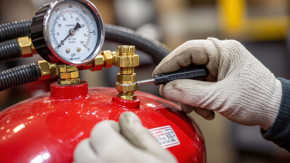
The air pressure switch controls when the compressor motor starts and stops by monitoring tank pressure and actuating at set cut-in and cut-out points, with the differential defining the gap between those settings.
Incorrect adjustments can create safety hazards, premature equipment wear, and energy inefficiency, and may prevent relief valves from protecting the system.
Typical components and terms to understand before making changes include the cut-in, cut-out, differential, and the relief valve.
Function of the pressure switch in an air compressor system
A pressure switch acts as the automatic control that starts and stops an air compressor by sensing tank pressure and opening or closing an electrical circuit at preset cut-in and cut-out values.
Proper adjustment guarantees consistent system pressure, prevents motor short-cycling, and protects downstream equipment from overpressure or insufficient air supply.
It monitors pressure, triggers motor control, and permits technicians to learn how to adjust air pressure switch on air compressor for reliable operation.
Risks of incorrect pressure switch settings (safety, equipment damage, inefficiency)
Incorrectly set pressure switches create clear and immediate risks: unsafe overpressurization, frequent motor cycling, and inefficient system operation.
Excessive pressure can rupture tanks or lines; too-low settings reduce tool performance.
Rapid on/off cycles overheat motors, shorten compressor life, and increase energy use.
Misadjustment also raises maintenance frequency and downtime, compromising workplace safety and productivity.
Typical components and terminology (cut-in, cut-out, differential, relief valve)
Understanding an air pressure switch’s key parts clarifies how pressure regulation and safety are achieved.
The cut-in is the lower threshold that starts the compressor; cut-out is the upper threshold that stops it. Differential equals the gap between cut-in and cut-out.
A relief valve provides overpressure protection, venting excess air if the switch or controls fail, ensuring system safety and preventing damage.
Required Tools, Equipment, and Safety Precautions
A concise list of tools and materials—wrenches, screwdrivers, replacement parts, and a pressure gauge—should be prepared before any adjustment.
The technician must wear appropriate PPE (safety glasses, gloves, ear protection) and arrange a clear, well-lit workspace.
Before touching the switch, power should be isolated, the tank fully depressurized, and lockout/tagout procedures applied.
Tools and materials checklist
Several basic hand tools, a few specialized items, and appropriate safety gear are required before adjusting an air compressor pressure switch.
The checklist specifies tools, replacement parts, and precautionary items to verify functionality and guarantee correct settings without causing damage.
- 1/4″ and 3/8″ nut drivers, adjustable wrench, screwdriver
- Replacement pressure switch or springs, pressure gauge
- Thread sealant, electrical tape, multimeter
Personal protective equipment and safe workspace setup
Appropriate personal protective equipment (PPE) and a cleared, well-lit workspace are essential before any pressure-switch adjustment; they protect against electrical shock, flying debris, and sudden air release.
Recommended PPE includes safety glasses, hearing protection, insulated gloves, and steel-toe footwear.
Keep tools organized, remove tripping hazards, guarantee adequate ventilation, and position a stable work surface.
Maintain clear egress and emergency access.
Pre-adjustment safety steps (power isolation, depressurize tank, lockout/tagout)
Begin by isolating all energy sources to guarantee the compressor cannot start or build pressure during the procedure: disconnect electrical power at the breaker or unplug the unit, close any supply valves, and verify power is off with a properly rated voltage tester.
Next, fully depressurize the tank via drain valves and pressure relief; apply lockout/tagout devices and post warning notices before proceeding.
How to Read Your Compressor’s Pressure Switch and Specifications
The technician locates the pressure switch and its access points on the compressor housing before any adjustments.
Manufacturer labels and wiring diagrams are examined to confirm electrical connections and identify the switch’s marked settings.
Finally, the factory cut-in and cut-out pressures and the listed allowable adjustment range are noted to set safe operating limits.
Locating the pressure switch and access points
Locating the pressure switch and its access points requires a quick visual survey of the compressor’s exterior: the switch is typically mounted near the motor or tank outlet and enclosed in a small rectangular or round housing with an electrical conduit and air fittings attached.
Identify the housing cover, external adjustment nuts/screws, nearby pressure port, and any service access panels for safe, direct access during maintenance.
Interpreting manufacturer labels and wiring diagrams
After identifying the pressure switch and access points, attention turns to the manufacturer labels and wiring diagrams that define its settings and safe operation.
Labels list model, voltage, maximum pressure, and adjustment limits.
Wiring diagrams show power, motor, and control terminals plus grounding.
Interpret symbols, wire colors, and ratings; confirm compatibility with compressor and electrical supply before any adjustments or maintenance.
Determining factory cut-in/cut-out and allowable adjustment range
One key step is identifying the pressure switch’s factory cut-in and cut-out settings, which indicate the minimum and maximum tank pressures at which the motor will start and stop.
The technician consults the switch label, compressor manual, or model datasheet to confirm those values and the permitted differential adjustment.
Adhering to the manufacturer’s allowable range prevents motor short-cycling and unsafe overpressure.
Step-by-Step Procedure to Adjust the Pressure Switch
The following step-by-step procedure guides the user through preparing the compressor, measuring existing cut-in and cut-out pressures with a gauge, and making targeted adjustments to the primary (cut-in) and secondary (differential/cut-out) screws.
It then covers safe reassembly, restoring power, and testing multiple start-stop cycles to confirm settings.
Each step emphasizes safety, accurate measurement, and small incremental changes to avoid overshooting the desired pressures.
Step 1 Prepare the compressor for adjustment
Begin by ensuring the compressor is powered down and isolated from its air and electrical supplies to prevent accidental starts or pressure buildup during adjustment.
Drain tank pressure fully via the drain valve.
Lock out and tag electrical sources.
Allow components to cool.
Gather required tools, safety glasses and gloves.
Confirm the pressure switch cover is accessible and unobstructed before proceeding.
Step 2 Verify current cut-in and cut-out pressures with a gauge
A precision gauge is connected to the compressor outlet to determine the existing cut-in and cut-out pressures before any adjustments are made.
The operator observes multiple run cycles, noting pressure at motor start (cut-in) and stop (cut-out). Readings are recorded, compared to desired settings, and checked for fluctuation or hysteresis issues.
Any abnormal values prompt inspection before adjustment.
Step 3 Adjust the cut-in pressure (primary screw) detailed steps
Raise or lower the primary screw to set the compressor’s cut-in pressure, using small, measured turns while monitoring the gauge and noting the motor’s start point.
Power off then loosen the locknut, make one-quarter to half-turn increments, restore power, and observe restart pressure.
Repeat until desired cut-in is reached.
Retighten locknut, verify stability through several cycles, and secure the cover.
Step 4 Adjust the differential / cut-out pressure (secondary screw) detailed steps
Now adjust the secondary (differential) screw to set the cut-out pressure, working in small increments and monitoring the gauge so the compressor stops at the desired higher pressure.
Turn the secondary screw clockwise to increase cut-out, counterclockwise to decrease.
Make quarter-turn adjustments, allow pressure to stabilize between changes, and record settings.
Confirm the differential remains within manufacturer limits to prevent short cycling.
Step 5 Reassemble, restore power, and test several cycles
Carefully reassemble the pressure switch cover and secure all screws and conduit fittings to restore the assembly to its original condition; reconnect power only after confirming the switch, wires, and strain reliefs are properly seated and no tools remain inside the panel.
Restore power, observe initial pump start/stop. Cycle the compressor several times, watch pressures, listen for abnormal noises, and verify cut-in/cut-out actions are consistent before concluding the procedure.
Step 6 Fine-tune and confirm stable operation
Proceed to fine-tune the pressure switch settings and confirm stable operation by making small, measured adjustments while observing multiple full pump cycles.
Verify consistent cut-in and cut-out pressures, listen for unusual sounds, and watch for air leaks or rapid cycling that indicate further correction is needed.
Record final settings, recheck safety valve and gauge accuracy, and monitor over several days to guarantee reliable, leak-free performance.
How to Diagnose Common Problems and When to Replace the Switch
Typical symptoms of a failing pressure switch include erratic cut-in/cut-out behavior, failure to start or stop the compressor, and visible corrosion or burned contacts.
Electrical troubleshooting should focus on testing continuity, verifying proper voltage, and cleaning or replacing dirty contacts to restore reliable operation.
If mechanical wear, repeated failures after adjustment, or internal arcing is evident, replacement of the switch is recommended.
Symptoms of a failing pressure switch
Recognize failing air compressor pressure switches by their telltale operational changes: the compressor may cycle erratically, fail to cut in or out at the set pressures, run continuously, or show inconsistent tank pressure readings.
- Rapid short cycling or unusually long runs
- Pressure never reaches cutoff or never drops to cut-in
- Fluctuating gauge readings or inability to hold pressure
Troubleshooting electrical issues and contact cleaning
Begin by isolating the compressor from power and visually inspecting the pressure switch assembly for burned, pitted, or loose contacts and for damaged wiring; these signs often indicate electrical faults that cause erratic cycling or failure to actuate.
Test continuity with a multimeter, clean contacts with contact cleaner and a non‑abrasive brush, tighten terminals, and verify coil and relay operation.
Replace the switch if corrosion or heat damage persists.
When adjustment won’t fix the problem replacement indicators
If adjusting the pressure switch fails to restore reliable operation, persistent or specific fault signs indicate the switch itself likely needs replacement.
Indicators include intermittent cycling despite correct settings, burned or pitted contacts, tripped thermal overloads, corrosion or moisture inside the housing, inconsistent cut-in/cut-out pressures verified with a gauge, and failed continuity tests.
Replace the switch when multiple indicators persist.
Optimal Settings for Different Applications
Ideal pressure settings vary by use: home workshop compressors typically run 90–120 psi, while painting, pneumatic tools, and industrial systems often require specific ranges within or above that band.
Selection should account for tank size and duty cycle to guarantee the compressor can maintain target pressure without excessive cycling.
Users must also consider pressure drop across hoses and fittings when setting cut-in and cut-out points.
Recommended pressure ranges for home workshop compressors
For a home workshop, selecting the correct pressure range depends on the tools in use and the tasks performed.
Typical compressors are set between 40–90 psi: lower end (40–60 psi) suits airbrushes, brad nailers, and inflating tires; midrange (60–80 psi) fits most staplers and finish nailers; higher home-use tasks may require up to 90 psi.
Always confirm tool manufacturer recommendations.
Recommended settings for painting, pneumatic tools, and industrial use
Different applications demand specific pressure and cut-in/cut-out settings to guarantee consistent performance and tool longevity. Painting: 40–60 PSI, cut-in 40, cut-out 60. Pneumatic tools: 90–120 PSI, cut-in 90, cut-out 120. Industrial: 100–150 PSI, cut-in 100, cut-out 150.
| Application | Pressure (PSI) | Cut-in/Cut-out |
|---|---|---|
| Painting | 40–60 | 40 / 60 |
| Pneumatic | 90–120 | 90 / 120 |
Adjusting for tank size, duty cycle, and pressure drop considerations
Adjusting pressure settings requires consideration of tank capacity, compressor duty cycle, and expected pressure drop during use.
For small tanks, increase cut-in pressure slightly to reduce short-cycling; large tanks allow wider bands.
For heavy duty or continuous use, lower cut-out margins to prevent overload.
Account for tool-specific pressure drop; adjust differential so delivered pressure remains within tool requirements under load.
Common Mistakes and How to Avoid Them
Careful attention to common errors helps prevent damage and maintain reliable compressor operation.
Over-tightening adjustments, ignoring the differential that causes short cycling, and skipping safety checks or proper testing are frequent sources of problems.
The following section outlines how to recognize and avoid each of these mistakes.
Over-tightening adjustments and exceeding safe limits
Over-tightening the pressure switch or pushing settings beyond the manufacturer’s specified range can quickly create safety hazards and damage the compressor.
Technicians should recognize that turning adjustment nuts or screws past resistance does not improve performance but increases the risk of valve failure, pressure relief activation, or burst fittings.
Follow specified torque, use calibrated tools, verify settings incrementally, and consult manuals to prevent mechanical stress and voided warranties.
Ignoring differential and creating short cycling
Ignoring the pressure differential—the gap between cut-in and cut-out settings—often causes short cycling, where the compressor turns on and off frequently in rapid succession.
This wastes energy, stresses components, and shortens motor life. Technicians should set an appropriate differential for tank capacity and application, verify with repeated cycles, and adjust incrementally until run times are reasonable to prevent frequent starts.
Skipping safety checks and improper testing procedures
After addressing proper differential settings to prevent short cycling, attention must turn to safety checks and testing procedures that validate those adjustments.
Technicians often skip pressure relief, leak, and shutdown tests, then assume accuracy. This risks injury and equipment damage.
Always perform calibrated gauge verification, controlled startup/shutdown cycles, and relief valve activation.
Document results and repeat tests after any adjustment.
Maintenance Tips to Keep the Pressure Switch Accurate
A regular maintenance routine helps preserve pressure switch accuracy and extend service life.
Technicians should inspect components on a set schedule, clean and lubricate moving parts, protect connections from moisture and debris, and watch for signs of wear.
Periodic calibration with documented records guarantees settings remain reliable and aids troubleshooting.
Routine inspection schedule and what to look for
While routine inspections vary with usage and environment, a consistent schedule—weekly for heavy-use systems, monthly for moderate use, and quarterly for light-duty compressors—helps guarantee the pressure switch remains accurate and reliable.
Inspect for mechanical wear, electrical connectivity, and pressure calibration drift. Address identified issues promptly to prevent malfunction.
- Check for loose terminals and frayed wiring
- Verify setpoints against a gauge
- Inspect actuator and linkage for play
Cleaning, lubrication, and protecting from moisture or debris
Keep the pressure switch free of dirt, oil, and moisture to preserve its sensitivity and prevent premature failure.
Periodically clean external surfaces with a dry brush and lint-free cloth; avoid solvents that damage diaphragms or seals.
Lightly lubricate moving metal linkages with manufacturer-approved oil.
Install protective covers, desiccant breathers, or drain nearby condensate traps to prevent moisture and debris ingress.
Calibrating periodically and keeping records
Following cleaning and moisture control, pressure switch calibration should be scheduled at regular intervals to verify setpoints and hysteresis.
Technicians perform checks using a calibrated gauge, adjust deadband and cut-in/cut-out as needed, document measured values, dates, and actions, and note component wear.
Maintaining a log enables trend analysis, timely replacements, and compliance with safety or warranty requirements.
When to Call a Professional and Estimated Costs
If the adjustment involves exposed wiring, failed pressure switches, or suspected motor or tank issues, a licensed electrician or HVAC/air‑compressor specialist should be contacted.
Professionals typically diagnose and repair such problems in one to three hours, with costs split between labor and parts—expect diagnostic fees plus hourly labor and a replacement switch or fittings if needed.
Estimated total costs commonly range from modest parts and a short service call to several hundred dollars for more complex electrical or compressor repairs.
Scenarios requiring licensed electricians or HVAC/air-compressorspecialists
Recognize situations where a do-it-yourself approach risks safety, equipment damage, or code violations and call a licensed electrician or HVAC/air-compressor specialist.
Examples: exposed or frayed wiring, circuit modifications, persistent tripping, motor or starter replacement, pressure switch failure with overheating, refrigerant or compressor core issues, poor grounding, or system diagnostics beyond basic pressure adjustments.
Professionals guarantee code compliance and safe repairs.
Typical service time and cost breakdown (parts vs labor)
After identifying scenarios that require a licensed electrician or HVAC/air-compressor specialist, attention turns to typical service times and cost breakdowns so owners can judge when professional help is cost-effective. Typical repairs take 0.5–3 hours; parts often 30–70% of total. Consider warranty, safety, and complexity before hiring.
| Task | Time | Cost Split |
|---|---|---|
| Minor adjustment | 0.5–1 hr | Labor 60% |
| Switch replacement | 1–2 hr | Parts 50% |
| Electrical repair | 2–3 hr | Labor 70% |
| Diagnostics | 0.5–1 hr | Labor 80% |
Conclusion
In sum, the guide gently suggests that tending the compressor’s pressure switch is less a chore than a discreet maintenance ritual: with suitable tools, cautious procedure, and modest patience, one may subtly coax accurate cut-in and cut-out behavior from the machine. Minor malfunctions often yield to careful diagnosis, while persistent faults quietly request professional attention. Regular, considerate upkeep preserves performance and prolongs service life, safeguarding both equipment and those who rely upon it.