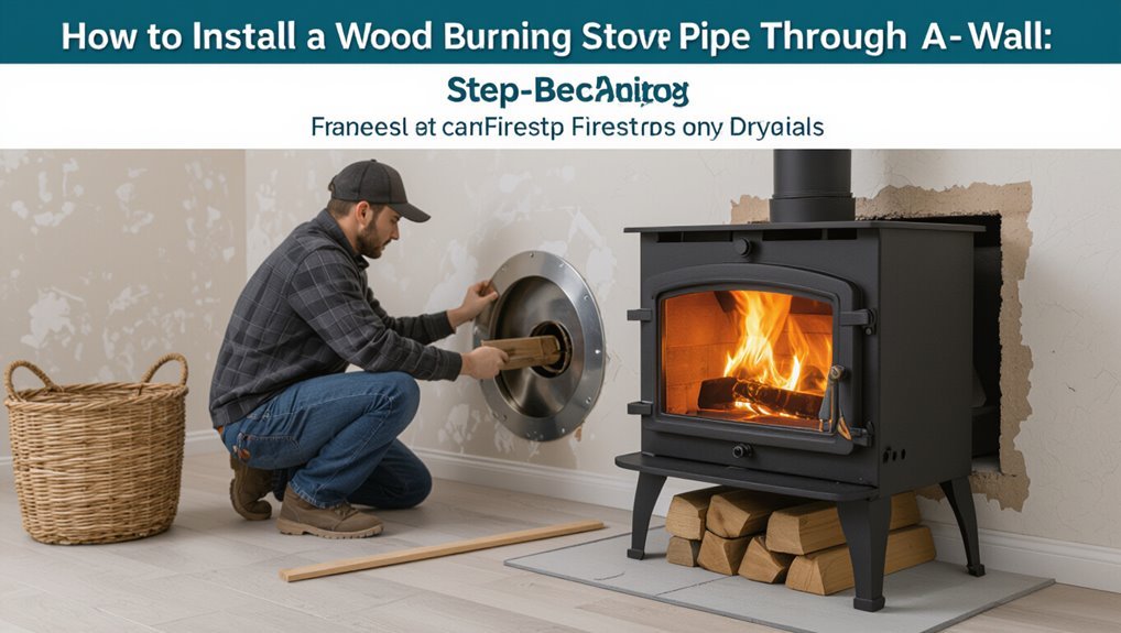
How to Install a Wood Burning Stove Pipe Through a Wall: Step-by-Step
To install a wood burning stove pipe through a wall, first measure accurately and mark the stove’s centerline, ensuring to check the locations of studs, wiring, and plumbing. Next, cut the wall opening to fit a rated wall thimble or insulated sleeve, frame it with blocking, and securely install the thimble plumb to the structure. Insert the listed stovepipe or insulated chimney through the thimble with the appropriate upward slope, pack around it with noncombustible insulation, and seal it with high-temperature sealant. Finally, complete the installation with exterior flashing, a storm collar, and a cap. It is recommended to obtain inspections and permits for full compliance with safety standards.
Who This Guide Is For and What You’ll Learn
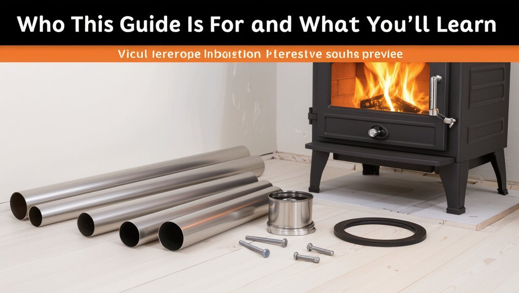
For homeowners, DIY enthusiasts, and small contractors planning to install a wood stove through an exterior wall, this guide outlines the essential steps, safety considerations, and code-related requirements needed to complete a compliant, weatherproof passthrough.
It addresses skill levels, necessary tools, and materials while clarifying when professional assistance is advisable.
Readers will learn heat-clearance principles, wall-penetration techniques, flashing and sealing methods, structural support basics, and how to interpret relevant building codes and manufacturer instructions.
The focus is practical instruction and risk mitigation; it does not replace inspections, certified installer involvement when required, or the quick checklist covered in the next section.
Quick Checklist: Wall‑Through Stove Pipe Installation
The checklist begins with precise Measure and Mark steps to locate the pipe and maintain clearances.
Next comes Cut and Frame, ensuring a correctly sized opening and a fire‑safe framed sleeve.
Finally, Seal and Insulate the penetration to prevent drafts, moisture, and heat transfer.
Measure And Mark
Accurate measurements and clear markings are essential before cutting a wall for a through‑wall stove pipe. The installer measures pipe diameter, required clearance, wall thickness, and centerline height from finished floor. Measurements are double‑checked against stove and pipe manufacturer specifications. Markings are transferred to both interior and exterior surfaces to guarantee alignment.
Reference studs, wiring, and plumbing are noted to avoid hidden obstructions. A level and square establish true vertical and horizontal guides. All marks are labeled with their purpose and measurements to guide the next step and to prevent errors during cutting and framing.
- Verify pipe diameter and clearance
- Locate and mark centerline
- Note wall thickness and obstructions
- Label marks with purpose and dimensions
Cut And Frame
With centerlines and obstruction notes in place, cutting begins by confirming stud locations and rechecking clearances to combustibles. A pilot hole through the drywall verifies alignment, then a reciprocating saw or hole saw cuts the finished opening to size. Remove insulation or blocking within the stud bay until the full pipe path is unobstructed.
Frame the opening with appropriate fire‑rated framing components, installing a header and trimmer studs as needed to support the wall structure. Make sure the framed opening matches the stove pipe manufacturer’s required clearances and dimensions. Debris is cleared and temporary supports removed before proceeding.
Seal And Insulate
After verifying clearances and framing, attention turns to sealing and insulating the wall penetration to prevent heat transfer, drafts, and moisture intrusion.
The installer fits a fire‑rated thimble and centers the pipe, then applies high‑temperature silicone at the interior and exterior gaps.
Noncombustible insulation, such as rock wool, fills any remaining cavity around the thimble without compressing.
An exterior flashing and chimney cap complete the weatherproofing.
Finally, joints are inspected for continuous seals and correct clearances.
- Install fire‑rated thimble and secure to framing
- Pack noncombustible insulation evenly
- Seal gaps with high‑temp sealant
- Add exterior flashing and cap
Permits, Codes, and Safety Rules for Wall‑Through Installs
Before beginning a wall‑through stove pipe installation, local building codes must be consulted to confirm clearances, materials, and chimney requirements.
The installer should determine which permits are required and obtain them from the relevant municipal authority.
Compliance with code and permit conditions reduces inspection delays and guarantees the installation meets safety standards.
Local Building Codes
Why consult local codes before cutting a hole in an exterior wall? Local building codes specify clearances, approved materials, termination locations, and firestopping requirements; compliance guarantees safety and legal occupancy.
Inspectors enforce standards that vary by jurisdiction, climate, and construction type. Installers must reference code editions and any local amendments, coordinate with fire and zoning rules, and verify manufacturer instructions align with code. Failure to follow local codes can require costly corrections.
- Confirm required clearances to combustibles and wall assemblies
- Verify approved pipe types and wall thimble specifications
- Check allowable exterior termination distances and heights
- Guarantee prescribed fireblocking and insulation methods
Required Permits
Who must obtain permits and what scope do they cover? Homeowners or contractors installing a wood stove pipe through an exterior wall typically must obtain permits.
Permits verify compliance with local building, fire, and mechanical codes, covering chimney clearances, wall thimble construction, support, flashing, and termination height.
Applications require plans, specifications, and inspection fees.
Inspectors assess installation at staged points and after completion; modifications may be required.
Failure to permit can result in fines, denied insurance claims, or mandated removal.
Always contact the local building department before work begins to determine specific permit types, fees, and required inspections.
Through‑Wall vs Through‑Roof Venting: Pros and Cons
When choosing between through‑wall and through‑roof venting, homeowners must weigh installation complexity, draft performance, and long‑term maintenance requirements.
Through‑wall vents offer simpler installation and lower upfront cost but may suffer reduced draft and increased risk of smoke backflow in certain weather.
Through‑roof systems generally provide superior draft and reduced creosote buildup yet demand more complex flashing, support, and higher expense.
Both require adherence to local codes and proper sealing to prevent leaks.
Selection depends on roof height, prevailing winds, aesthetic preference, and budgetary constraints.
- Installation difficulty
- Draft quality
- Maintenance needs
- Cost and aesthetics
Required Clearances: Distances to Combustibles
Required clearances around a wood stove pipe are critical safety measures that specify minimum distances between the hot pipe and any combustible material—walls, ceilings, furniture, insulation, and structural members—to prevent ignition and allow safe heat dissipation.
Local building codes and the stove manufacturer set specific clearances; typical single-wall pipe requires larger offsets than insulated or double-wall systems.
Clearances apply horizontally and vertically and around wall thimbles and ceiling penetrations.
Noncombustible shields, listed heat shields, or increased standoffs can reduce required distances if installed per code and manufacturer instructions.
Always verify measurements with the authority having jurisdiction before installation.
Stove Pipe Types and Chimney Components for Wall Installs
The section outlines common stove pipe types—single-wall, double-wall, and insulated pipe—and their suitability for wall installations.
It also explains essential chimney components such as thimbles, wall supports, firestops, and flashing.
Comparisons focus on heat transfer, clearance requirements, and installation implications.
Pipe Types Overview
Choosing the correct pipe and chimney components for a wall installation hinges on understanding differences in materials, clearance requirements, and how each part manages heat and creosote. The overview distinguishes single-wall, double-wall, and insulated prefabricated systems, noting trade-offs in installation space, heat radiation, and draft stability.
Material choices (black steel, stainless) affect longevity and maintenance. Fit, joint type, and required clearances determine suitability for passing through combustible walls versus noncombustible chases.
- Single-wall stovepipe: compact, higher radiative heat, larger clearances
- Double-wall: reduced clearance, moderate insulation
- Class A insulated: best draft, minimal clearance
- Material: steel vs. stainless considerations
Chimney Components Explained
Moving from material and clearance considerations to specific parts, the chimney assembly for a wall installation is best understood as a system of interlocking components that control heat, maintain draft, and protect surrounding structure.
Key elements include single- or double-wall stovepipe connecting the stove to the wall thimble; a wall thimble or prefab wall pass-through creating a sealed, insulated opening; an insulated chase or insulated pipe section to maintain flue temperature; a chimney cap to keep out weather and animals; storm collar and flashing to seal roof penetrations; and support brackets or roof lead for structural stability and required clearances.
Stove Pipe Sizes and How to Choose the Right One
Several common stove pipe diameters exist, and selecting the correct size hinges on matching the stove outlet, chimney connection, and required draft performance. Choice affects safety, efficiency, and creosote buildup; undersized pipes restrict draft, oversized pipes cool flue gases.
Measure the stove collar and confirm manufacturer recommendations. Consider run length, number of elbows, and elevation changes when balancing diameter and draft. Local codes may mandate minimum sizes for specific appliances. Adapter pieces should be avoided where possible; when necessary use properly rated adapters.
- Measure stove collar and chimney inlet precisely
- Follow manufacturer and code requirements
- Favor full‑diameter continuous runs
- Minimize restrictive fittings
Materials & Tools for a Wall‑Through Stove Pipe Job
The section lists the essential materials for a safe wall-through stove pipe installation, including double-wall pipe, wall thimbles, high-temperature sealant, flashing, and appropriate insulation or firestop components.
It also provides a concise recommended tools list—drill, hole saw, level, sheet metal screws, caulking gun, and protective gear—needed to complete the job correctly.
Readers are reminded that using specified materials and proper tools reduces fire risk and guarantees a code-compliant installation.
Essential Materials Required
For a safe, code‑compliant wall‑through stove pipe installation, a clear checklist of materials and tools is essential: double‑ or triple‑wall stove pipe sections rated for the stove type, a wall thimble or insulation spacer, high‑temperature stovepipe sealant and fasteners, a chimney cap, clearance‑reducing shields if required by local code, heat‑resistant flashing and exterior finish plates, appropriate firestop and wall penetration materials, a level, tape measure, drill, metal snips, screwdrivers, and personal protective equipment (gloves, eye protection, and a respirator when cutting or sealing).
Key materials include fire‑rated pipe, thimble, sealant, flashing, caps, and approved fasteners.
- Certified stove pipe sections
- Wall thimble/insulation spacer
- Heat‑resistant flashing and cap
- Firestop and exterior finish plate
Recommended Tools List
When preparing to install a wall‑through stove pipe, a focused set of hand and power tools plus safety equipment guarantees the job proceeds accurately and safely; key items include a drill with metal bits, tin snips, a reciprocating saw or hole saw sized for the wall thimble, a level and tape measure, a square, caulking gun for high‑temperature sealant, clamps, screwdrivers, and a torque‑capable driver for fasteners.
Additional recommended items: masonry bit and hammer drill for brick or block, metal file or deburring tool, abrasive wheel or flap disc for pipe edges, heat‑resistant sealant, high‑temp silicone gloves, safety glasses, hearing protection, and a stud finder.
Measuring the Wall and Planning the Pipe Path
Before any cutting or drilling begins, one person should accurately measure the wall thickness, stud locations, and the vertical alignment needed for the flue; these dimensions determine the pipe length, clearance requirements, and exact hole placement.
The installer records height from the stove outlet to the wall centerline, notes exterior siding offsets, and verifies usable interior space for connector bends. Consider thermal clearance to combustibles and required passthrough components when plotting the path. Account for slight deviations to preserve draft and service access. Finalize measurements on a diagram before marking the wall.
- Pipe length and segment layout
- Clearance distances
- Exterior offset allowances
- Service and inspection access
How to Locate Studs, Wiring, and Plumbing Safely
Before cutting, the installer locates studs with a reliable stud finder and confirms spacing to guarantee a secure pipe collar mount.
Next, they use an electronic detector to identify live wiring and trace plumbing runs, taking extra care where utilities cluster.
Finally, hazards are clearly marked and the planned hole is positioned to avoid structural members and concealed services.
Find Studs Accurately
Accurately locating studs, wiring, and plumbing is essential to safely cutting a hole for stove pipe through a wall. The installer uses stud-finding tools and measuring standards to mark safe drilling and cutting zones. Techniques emphasize multiple confirmation methods and respect for building layouts to prevent structural or service damage.
- Scan with a calibrated electronic stud finder for wood or metal framing
- Verify stud edges by measuring 16 or 24 inches from a known corner
- Confirm locations with small exploratory pilot holes where permissible
- Mark clear centerlines and avoid areas reserved for utilities pending separate detection
Detect Wires And Pipes
Scan walls systematically to identify live electrical wiring and plumbing runs before cutting for stove pipe, using a combination of electronic detectors, visual inspection of fixtures, and knowledge of typical service routing.
Use a calibrated stud finder with live-wire detection, sweeping slowly and marking consistent signals. Inspect adjacent rooms, outlets, switches, and visible plumbing to infer hidden paths.
Probe shallowly with a thin drill bit or drywall awl in noncritical areas to confirm absence of conductors. For complex systems or uncertainty, consult building plans or a licensed electrician/plumber.
Record findings clearly to inform safe placement and avoid concealed utilities.
Mark And Avoid Hazards
How can hazards be marked and avoided so wall penetrations for a stove pipe remain safe? The installer surveys stud locations, electrical runs, and plumbing using a reliable scanner and visual inspection. Findings are marked with pencil and tape, noting depth and clearance. Any questionable signals prompt opening a small inspection hole to verify. Where utilities exist, the route is adjusted to maintain required clearances and firestopping. Documentation and photos are kept for future reference.
- Confirm studs, joists, and noggings before cutting
- Trace and label electrical cables and junctions
- Locate water and gas pipes; maintain setbacks
- Use temporary covers and tags during work
How to Size and Choose a Wall Thimble or Firestop
When passing a stove pipe through a combustible wall, selecting a correctly sized thimble or listed firestop is essential to maintain required clearances and prevent heat transfer to surrounding materials.
Measure the stove pipe outer diameter and choose a thimble matching that O.D.; for double-wall or insulated pipe, size to the outermost surface.
Confirm the chosen unit is listed for the pipe type and stove model, and meets local code clearance requirements.
Use adjustable or insulated thimbles where wall thickness varies.
Verify gasketing or sealing instructions, and document manufacturer clearances.
Never reduce required clearances by field modifications.
Exterior Wall Chase and Chase Pan Options
Exterior wall chases and chase pans provide protected pathways where stove pipe penetrates an exterior surface.
The discussion contrasts common chase pan types—recessed, flush, and insulated enclosures—and their suitability for different siding and clearance requirements.
Attention is given to maintaining required exterior wall clearances and weatherproofing to prevent heat transfer and moisture intrusion.
Chase Pan Types
In choosing a through-wall flue, the chase pan serves as the watertight connection between the stove pipe and the siding, preventing moisture intrusion and providing a clean finished appearance.
Different chase pan types suit varied siding materials and rooflines: pressed metal pans fit narrow clearances, adjustable pans allow slope compensation, stainless pans resist corrosion near salt air, and painted pans match aesthetics.
Proper flange sizing and flashing integration matter most.
Selection balances durability, weatherproofing, and installation simplicity. Contractors evaluate pan depth, gasket presence, and compatibility with pipe diameter before finalizing the wall penetration method.
- Pressed metal pans
- Adjustable slope pans
- Stainless steel pans
- Painted finish pans
Exterior Wall Clearance
Selecting the appropriate chase pan informs the required exterior wall clearance around the stove pipe and the choice of chase construction. Exterior wall clearance must meet manufacturer and local code distances from combustible siding, framing, and trim; noncombustible cladding or an insulated chase reduces required setbacks.
Options include a minimum-clearance open chase, lined chase with insulation and firestops, or a prefabricated insulated chase pan that provides a weatherproof passage and maintains air gap. Flashing and sealing prevent moisture intrusion while preserving clearance.
Final design documentation should specify clearances, materials, and inspection points to guarantee safety and compliance.
Designing the Horizontal Run: Slope, Length, Support
When planning the horizontal run of a wood stove pipe through a wall, the installer must balance draft performance, safety clearances, and structural support.
The run should slope upward 1/4″ to 1/2″ per foot toward the chimney to prevent creosote and condensation pooling. Keep horizontal length minimal; each additional foot degrades draft and increases soot accumulation. Maintain required clearances from combustible materials and pass through a rated wall thimble or insulated sleeve. Support the pipe at intervals with noncombustible brackets, allowing slight movement for thermal expansion and easy inspection or removal.
- Maintain 1/4″–1/2″ per foot rise
- Minimize horizontal length
- Use rated thimble/sleeve
- Provide noncombustible supports
When to Use an Offset Elbow vs a Straight Run
Although a straight run offers the best draft and simplest installation, an offset elbow becomes necessary when obstacles, offsets in framing, or clearance requirements prevent a direct line through the wall and chimney.
An offset is chosen to navigate studs, pipes, ductwork, or masonry while maintaining required clearances from combustibles.
Use short, gradual offsets rather than multiple abrupt bends to minimize resistance and soot accumulation.
Consider available horizontal space, exterior termination location, and code limits on angled sections.
If an offset introduces excessive length or complex angles, reevaluate placement or use approved adaptor components to preserve safety and serviceability.
Calculating Draft and Minimum Chimney Height
In calculating draft and minimum chimney height, the goal is to guarantee sufficient natural updraft to carry combustion gases out of the stove without creating excess air leakage or backpuffing. Draft depends on chimney height, temperature differential, and flue diameter; taller, warmer chimneys draft better.
Minimum heights follow code: typically 3 feet above roof where it meets ridgeline rules, and at least 15 feet measured from the stove outlet to the chimney top with horizontal offsets limited. Proper sizing prevents smoke spillage and improves combustion efficiency.
- Determine required flue size for stove output
- Compute effective height including offsets
- secure 2-3 inch temperature rise
- Verify local code clearance
Preparing the Stove and Room for Installation
Clear the installation area and inspect the stove, flue components, floor protection, and surrounding walls for damage or noncompliant materials before any work begins.
Make certain the stove is empty, cooled, and disconnected from any existing flue. Remove combustible furnishings and hangings within recommended clearances.
Verify floor protection meets local code — replace or extend hearth pad if required. Lay down protective coverings for finishes and set aside necessary tools and fasteners.
Confirm adequate ventilation and access for installers. Review manufacturer instructions and permit requirements.
Plan pipe routing and component fitment to minimize on-site modifications and make certain a safe, code-compliant installation.
Marking and Cutting the Wall Safely and Accurately
With the stove staged and the work area prepared, attention turns to locating and cutting the wall opening for the pipe.
Measurements are taken from stove centerline and finished floor; framing, insulation, and siding are inspected.
A stud finder and level guarantee the hole avoids structural members and utilities.
The opening is marked to match the pipe or thimble diameter plus clearance.
Protective coverings and masks remain in place; a reciprocating saw or hole saw is used with steady control.
Debris is removed and edges are checked for square and smooth fit before proceeding.
- Verify centerline and clearances
- Locate studs and wiring
- Mark precise cut lines
- Cut slowly, remove debris
Installing the Interior Wall Thimble Securely
Secures the thimble into the prepared opening by orienting the inner collar flush against the interior wall and checking that the outer collar aligns with the exterior cutout; proper seating guarantees the required clearance to combustible materials is maintained.
The installer inserts the thimble straight, avoiding twists, until the flanges sit evenly.
Fastening follows manufacturer guidance: use corrosion-resistant screws through designated holes into studs or blocking, not just drywall.
Confirm the thimble is level and plumb before final tightening.
Trim any protruding insulation or framing that interferes with seating.
Recheck clearances and structural support once the thimble is fully secured.
Sealing and Insulating Around the Interior Pipe
Typically, once the thimble and pipe are fitted, attention turns to sealing and insulating the interior penetration to prevent drafts, heat loss, and moisture migration.
The installer applies non-combustible insulation around the pipe within the thimble, ensuring constant clearance to combustible framing. High‑temperature sealant or stove cement is used at the interior trim to create an airtight finish. Any gaps are filled while avoiding contact with the pipe surface. Finally, the decorative trim plate is attached, maintaining the required airspace.
- Use ceramic fiber or mineral wool for insulation.
- Apply rated high‑temp sealant sparingly.
- Maintain manufacturer clearance specs.
- Inspect for air leaks.
Attaching the Pipe to the Stove Flue Collar Correctly
Attention to flue alignment is essential before connecting the stove pipe to the flue collar to guarantee proper draft and to prevent stress on joints.
The pipe should sit squarely on the collar with no gaps or upward/sideways offset.
Once aligned, the connection must be fastened with the manufacturer-recommended screws or clamps to secure the assembly and maintain a tight seal.
Ensure Proper Flue Alignment
Align the stovepipe squarely with the stove’s flue collar so the male end seats fully into the collar and the joint sits flush without gaps or twisting.
The installer verifies axial and angular alignment to prevent drafts, soot buildup, and uneven stress on seams.
Visual and tactile checks confirm concentric fit; small adjustments correct misalignment before final securing.
Clearance to combustibles and wall penetration must remain consistent along the pipe run.
Proper alignment promotes efficient draw and reduces corrosion points.
If joins resist seating, inspect for deformities or obstructions and replace defective sections.
- Confirm concentric engagement
- Check axial straightness
- Inspect for obstructions
- Verify consistent clearances
Secure With Correct Fasteners
Consistently using the correct fasteners guarantees a secure, gas-tight connection between the stovepipe and the flue collar; the installer selects hardware rated for high temperatures and corrosion resistance, such as stainless steel screws or rivets specified by the stove manufacturer.
Fasteners must match pipe gauge and collar holes; oversize or short screws compromise seal and strength. Position screws evenly around the collar, typically three to four, tightening to manufacturer torque without deforming metal. Use high-temperature sealant or gasket where specified.
Inspect connections after initial firing and periodically thereafter, replacing any corroded or loosened fasteners to maintain safe operation.
Joining Stove Pipe Sections and Locking Joints
Properly joining stove pipe sections and locking their joints guarantees a safe, draft-efficient flue connection and prevents disassembly during operation.
Each segment should fit snugly with the male end inserted toward the stove to shed creosote and condensate.
Seam alignment, offset allowances, and access for inspection determine joint placement.
Fasteners and locking tabs stabilize connections without distorting pipe geometry.
- Verify male-female orientation for proper drainage.
- Engage factory crimps or bead locks fully before fastening.
- Use high-temperature-rated self-tapping screws at recommended intervals.
- Install locking bands or clips where code or manufacturer requires, avoiding overtightening.
Mounting Exterior Supports and Bracing the Run
When passing the stove pipe through exterior walls and along the outside of a building, secure supports and braces must be installed to maintain alignment, resist wind loads, and prevent sagging over time.
Exterior supports are fastened to structural elements using corrosion-resistant hardware and spaced according to pipe diameter and local code, typically every 3–6 feet for single-wall and per manufacturer for double-wall systems.
Use adjustable wall brackets, band straps, or pipe supports that allow thermal expansion while preventing lateral movement.
Anchor points should avoid penetrating weather barriers; use flashing-compatible mounts.
Inspect and tighten fasteners after initial heating cycles and seasonally thereafter.
Installing Exterior Flashing, Termination, and Cap
For exterior flashing, termination, and cap installation, the pipe exit must be weatherproofed, structurally supported, and terminated with a code-approved cap to keep water, debris, and animals out while allowing proper draft.
The installer fits a metal flashing plate against siding, secures a support box or wall thimble, and seals joints with high-temperature sealant.
A listed termination assembly is attached, set plumb, and braced to the wall support.
The cap is fastened per manufacturer instructions, maintaining required clearances and draft path.
Final inspection verifies fastening, clearance, and cap function.
- Fit flashing tight to siding
- Secure termination to support box
- Seal all joints with high-temp sealant
- Fasten cap per manufacturer
Weatherproofing the Exterior Penetration
Attention to exterior flashing details and proper use of high-temperature sealant guarantee the pipe penetration resists water and wind.
The surrounding cavity must be insulated and backfilled to prevent drafts and thermal bridging without compressing the insulation.
Clear instructions on flashing overlap, sealant bead placement, and insulation clearance help prevent leaks and maintain fire safety.
Exterior Flashing Details
Around the exterior penetration, properly installed flashing creates a continuous, weatherproof barrier between the stove pipe and the siding. The flashing should be layered to shed water, fabricated from corrosion-resistant metal, and fitted tightly to the pipe collar and wall plane.
It must direct runoff away from joints and prevent capillary action behind siding. Fasteners should be placed under upper laps and sealed when exposed. Inspect for gaps, deformation, or paint deterioration periodically and replace compromised sections promptly to maintain integrity.
- Step flashing integrated with siding reveals
- Base flashing angled to shed water
- Counterflashing overlapping seams
- Stainless or aluminum material choice
Sealant And Insulation
When penetrating the wall, a continuous seal of high-temperature-rated sealant combined with non-combustible insulation prevents water ingress, air leakage, and thermal bridging at the stove pipe collar.
Exterior-grade silicone or specialized fireplace sealant fills gaps between the pipe and flashing; it must remain flexible and heat-resistant.
Inside the wall, mineral wool or ceramic fiber insulation packs around the pipe within the required clearance zone, avoiding combustible materials.
Backer rods can control sealant depth.
After curing, trim excess and apply a paintable, UV-stable coating if specified.
Periodic inspection and resealing maintain weatherproofing and prolong system integrity.
Fireproofing Combustible Siding and Finishes
To protect combustible siding and interior finishes where a stove pipe passes through a wall, install approved heat shields, noncombustible insulation, and properly rated wall thimbles to maintain required clearances and prevent heat transfer or ignition.
The installer makes certain exterior cladding is separated from the pipe by an air gap or metal flashing and uses cement board or mineral wool where pipe exits.
Fasteners and trim must be noncombustible.
Penetrations are sealed with high-temperature, noncombustible materials to block drafts and moisture without compromising clearance.
- Metal heat shield with specified air gap
- Cement board or masonry collar
- Mineral wool insulation
- High-temperature sealant
Inspecting Clearances and Final Safety Checks
The installer verifies that all clearance distances from combustibles meet the manufacturer’s specifications and local code requirements.
A thorough final inspection confirms joints, supports, and seals are secure and that the system drafts correctly.
Any discrepancies are corrected before the stove is placed into regular service.
Clearance Distances Checked
A thorough final inspection confirms all clearance distances around the stove pipe comply with manufacturer specifications and local codes, ensuring combustible materials, furniture, and structural elements maintain required separation.
The inspector verifies measured gaps at pipe, wall thimble, ceiling penetrations, and nearby objects, documenting any deviations and correcting installations before use.
Clearances are rechecked after shielding or insulation additions.
Visual and measured confirmation prevents heat transfer risks and supports permit compliance.
- Measure horizontal and vertical distances to combustibles.
- Confirm thimble and wall wrap positioning.
- Verify clearances to ceiling and rafters.
- Record measurements and corrective actions.
Final System Inspection
Following confirmation of correct clearances, the inspector proceeds to a thorough final system inspection that reevaluates all clearances and performs safety checks on operational components. The inspector verifies pipe stability, seals, and proper pitch, checks chimney connections, and confirms termination clearances. Draft, smoke, and carbon monoxide tests are conducted. Documentation of measurements and photos is completed. Any deficiencies are noted for immediate correction. After corrections, a final walkaround confirms secure mounts and no combustible contacts. The owner receives clear operating and maintenance instructions and a signed checklist.
| Item | Check | Result |
|---|---|---|
| Pipe | Secure | OK |
| Seal | Intact | OK |
| Draft | Test | OK |
| CO | Monitor | OK |
First‑Light Tests: Draft, Smoke, and Leak Checks
Usually, a careful first-light sequence confirms proper draft, reveals smoke behavior, and exposes any leaks before regular use begins.
The installer observes startup with small, seasoned kindling, noting how quickly the chimney establishes pull, whether smoke backs into the room, and whether joints remain tight.
Doors and dampers are cycled to confirm control response.
Exterior areas around the wall thimble are inspected for discoloration or odors that suggest heat transfer or leakage.
- Record initial draft strength and stability.
- Watch for any backpuffing or smoke odor indoors.
- Inspect all seams and wall penetrations for escaping smoke.
- Verify exterior flashings and clearances remain cool.
Routine Maintenance for Wall‑Through Stove Pipe Systems
Regularly scheduled maintenance keeps wall‑through stove pipe systems safe and efficient.
Inspect joints, fasteners, and wall thimbles monthly for looseness, corrosion, or gaps.
Clean creosote and soot from accessible pipe lengths and the chimney connector at intervals based on burn frequency and fuel type.
Verify clearance to combustibles remains compliant and remove any accumulated debris around the termination.
Replace any damaged gaskets, sealants, or firestop components promptly.
Test support brackets and wall penetration seals for integrity after severe weather or settling.
Document inspections and maintenance dates to track patterns and schedule professional chimney sweeps annually or as local codes recommend.
Detecting and Fixing Smoke and Draft Problems
Diagnosing smoke and draft problems begins with observing symptoms—smoke backflow, sluggish chimney draw, or odor in living spaces—and correlating them with recent changes in fuel, weather, or appliance condition.
The inspector evaluates airflow, checks for cold flues, inspects damper function, and verifies correct pipe slope and termination height.
Temporary tests include a smoke pencil or incense to trace flows and measuring draft with a manometer.
Common fixes focus on improving draft and combustion, adjusting fuel size and moisture, and eliminating external downdrafts by modifying termination or adding wind-resistant caps.
- Verify fuel dryness and correct loading practices
- Test draft under varied weather
- Confirm damper and air intake operation
- Inspect termination height and cap type
Repairing Leaks, Loose Joints, and Damaged Flashing
Inspectors frequently find leaks, loose joints, and damaged flashing at wall and roof penetrations where stove pipe passes through, because thermal cycles, settling, and weather expose weak seals and fasteners.
Evaluate sealant condition, fastener tightness, and flashing integrity. Tighten or replace loose pipe connectors and use high-temperature gasket or stove pipe cement for small gaps.
Replace corroded or torn flashing and reseal with compatible metal flashing and high-temperature sealant, ensuring proper overlap and drip edge.
Restore any deteriorated roof membrane and interior trim after repairs. Test for leaks by running the stove and checking for drafts, soot stains, or moisture intrusion.
Upgrades: Spark Arrestors, Dampers, and Cleanouts
Often, homeowners enhance safety and performance by adding spark arrestors, dampers, and cleanouts to stove pipe runs; these upgrades control ember ejection, regulate draft, and simplify ash removal, respectively.
Spark arrestors sit atop the chimney to catch hot debris; dampers fit inside the pipe to tune combustion and reduce heat loss; cleanouts provide accessible access for ash and creosote removal.
Selection should match pipe diameter and local codes. Proper installation preserves clearances and weatherproofing. Periodic inspection verifies function. Consider corrosion-resistant materials and easy-access placement for routine maintenance.
- Spark arrestor sizing and mesh
- Damper types and placement
- Cleanout access options
- Material and code compatibility
When to Call a Pro for Wall‑Through Installations
After addressing upgrades like spark arrestors, dampers, and cleanouts, homeowners should recognize when a wall‑through stove pipe installation exceeds DIY scope and requires a professional.
Complex wall assemblies, load‑bearing modifications, compromised or unknown wall materials, or multi‑flue routing demand a certified installer or mason.
If local codes require permits, inspections, or specific clearances, a pro makes certain compliance.
Signs of inadequate draft, persistent smoke intrusion, or proximity to combustible framing warrant expert assessment.
When roof penetration, firestop integration, or masonry chimney tie‑ins are involved, hire a technician experienced with UL listings and building‑code documentation to guarantee safety.
Cost Breakdown: Parts, Labor, and Estimates
For a wall‑through wood stove pipe installation, costs divide into parts, labor, and any required permits or inspections, each with predictable ranges that homeowners should budget for.
Typical parts—double‑wall pipe, thimble, flashing, and chimney cap—range from modest to premium prices depending on materials and lengths.
Labor varies by local rates and complexity; expect higher fees for tight access or fireblocking.
Permit and inspection fees are usually fixed by municipality.
Contingencies for unexpected structural or fireproofing work should be included in estimates.
- Parts: materials and flashing
- Labor: hourly or flat contractor rates
- Permits: municipal fees
- Contingency: unexpected work
Common Mistakes to Avoid During Installation
What common pitfalls threaten a safe and effective wall‑through stove pipe installation? Improper clearances, using single‑wall pipe where double‑or-insulated is required, and failing to maintain a straight, adequately pitched run can create fire and draft problems.
Incorrect hole sizing or flange placement weakens structural integrity and permits water intrusion.
Skipping appropriate firestop and thermostat‑rated supports risks heat transfer to combustibles.
Neglecting local code requirements or not consulting manufacturer instructions leads to noncompliant assemblies.
Poor sealing at joints causes smoke leakage.
Overlooking chimney termination height and obstruction clearance compromises draft and performance.
Each error increases hazard and may void warranties.
Documenting the Install for Permits and Resale
When preparing the installation for permits and future sale, the installer documents each step with dated photos, manufacturer labels, and a clear parts list to verify compliance and provenance. Records include permits, inspection reports, and receipts. Clear annotations indicate measurements, clearances, and installed model numbers. Documentation preserves warranty eligibility and supports accurate listing disclosures.
- Dated photos of stove, pipe joints, wall thimble, and clearance zones
- Copies of manufacturer manuals, serial numbers, and parts receipts
- Inspection certificates and signed permit approvals
- A concise install summary with measurements, installer contact, and date
Installing Through Masonry vs Framed Walls: Differences
How does passing a wood stove pipe through solid masonry differ from routing it through a framed wall? Masonry requires drilling a precise hole, using a masonry thimble or firestop plate, sealing with high‑temperature mortar or rated silicone, and ensuring the surrounding mass provides thermal buffering.
Framed walls require creating a framed sleeve, maintaining required clearances to combustibles, installing an insulated thimble or double‑wall passthrough, and adding firestops where plumbing or wiring may be nearby.
Masonry installations emphasize anchoring and sealing to prevent moisture; framed installations emphasize structural support, clearance shielding, and vapor/fire barriers.
Both must follow code, manufacturer instructions, and inspected permits.
Conclusion
A properly executed wall‑through stove pipe installation transforms home heating from a chore into a near‑mythic ritual of efficiency and warmth. Following codes, clearances, and manufacturer instructions prevents hazards and simplifies permitting. Whether through masonry or a framed wall, attention to flashing, firestops, and inspections saves time and money. Documenting the work protects resale value. With careful planning and professional help when needed, a safe, long‑lasting vented stove is entirely achievable.