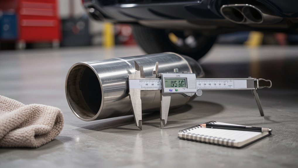
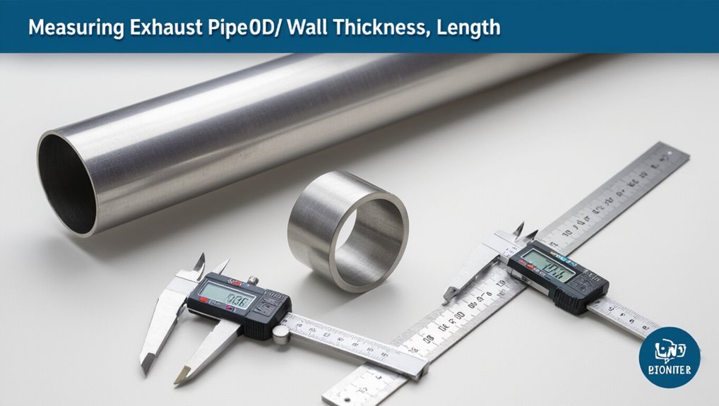
How to Measure an Exhaust Pipe: Easy Step-by-Step Guide
To measure an exhaust pipe accurately, follow these straightforward steps:
- Determine Outside Diameter (OD): Use calipers or a tape measure to measure the widest external points of the pipe.
- Find Inside Diameter (ID): Insert calipers or use flexible tape to measure the circumference, then divide by pi (approximately 3.14).
- Check Wall Thickness: Use a micrometer to measure, or calculate by subtracting ID from OD and halving the result.
- Measure Length: Measure along the centerline of the pipe, ensuring to account for any curves, and verify your measurements twice for accuracy.
By following these steps, you can effectively measure your exhaust pipe for any necessary repairs or modifications.
Which Exhaust Pipe Dimensions Matter: OD, ID, Wall, Length
Selecting the right exhaust pipe requires attention to four primary dimensions: outside diameter (OD), inside diameter (ID), wall thickness, and length.
The OD determines fit with clamps, slip joints, and adapters; it also influences external clearance. The ID dictates flow capacity and backpressure characteristics, affecting performance and sound.
Wall thickness impacts strength, rigidity, and thermal mass; thicker walls resist dents and corrosion but add weight.
Length governs routing, resonance, and installation compatibility with mufflers and hangers.
Accurate specification of each dimension guarantees proper mating, reliable operation, and predictable exhaust behavior across different vehicles and setups.
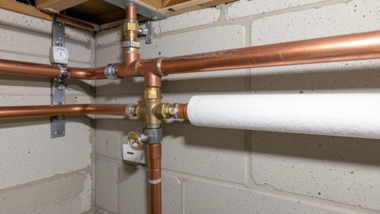
Which Tools You’ll Use to Measure an Exhaust Pipe
Measuring an exhaust pipe reliably requires a small set of accurate tools: a caliper for inside and outside diameters, a micrometer or thickness gauge for wall measurement, a tape measure or ruler for length, and a flexible measuring aid or feeler gauges for hard-to-reach sections and clearance checks.
A digital caliper offers quick, repeatable readings; Vernier calipers work where batteries aren’t available. A micrometer or ultrasonic thickness gauge provides precise wall readings without compressing thin metal.
Flexible steel tape or contour rulers adapt to bends. Feeler gauges or a bendable probe check gaps and mounting clearances.
Gloves and a marker aid safe, exact placement.
How to Measure Pipe Outer Diameter (OD)
The outer diameter (OD) of an exhaust pipe is the primary dimension used for fitment and mating with clamps, hangers, and adjoining sections; it is measured across the widest external points of the pipe’s circular cross-section.
To measure OD, place calipers or a tape measure perpendicular to the pipe axis and record the maximum external span. For oval or dented pipes, take multiple readings at different orientations and use the largest value for compatibility.
Include any external beads, flanges, or welded seams that affect fit. Report measurements in millimeters or inches, rounded to the nearest practical increment for components.
How to Measure Pipe Inner Diameter (ID)
Measuring an exhaust pipe’s inner diameter (ID) requires different tools and technique than the outer diameter.
One method uses calipers inserted carefully across the bore for a direct, precise reading.
For larger or irregular openings, a flexible tape can be wrapped inside and read against a ruler to estimate the ID.
Measure With Calipers
One reliable way to determine a pipe’s inner diameter is to use calipers, which provide direct, accurate readings when positioned correctly across the bore.
The technician selects vernier, dial, or digital calipers, zeroes them, then inserts the internal jaws gently into the pipe until they contact opposite inner walls.
Care is taken to keep the tool perpendicular to the axis to avoid skewed results. Multiple measurements at different depths confirm roundness and identify ovality.
The smallest consistent reading is recorded as the ID. Clean contact surfaces and repeat checks improve accuracy and reliability.
Use Flexible Tape
Wrap a flexible tape measure around the inner circumference of the pipe to determine its inner diameter indirectly. The technician presses the tape snugly against the pipe wall, reads the circumference, and divides by pi (3.1416) to calculate ID. This method suits irregular or worn edges where calipers struggle. Record measurements twice for consistency and use the average. Verify the tape lies flat and perpendicular to the pipe axis to avoid error. Apply arithmetic carefully and note units.
| Measurement | Circumference (in) | Calculated ID (in) |
|---|---|---|
| Trial 1 | 9.42 | 3.00 |
| Trial 2 | 9.45 | 3.01 |
| Trial 3 | 9.40 | 2.99 |
| Average | 9.42 | 3.00 |
How to Measure Pipe Wall Thickness Quickly
Quickly determining pipe wall thickness can save time and prevent costly mistakes when selecting replacement parts or evaluating wear.
A caliper or micrometer measures outer and inner diameters; subtract inner from outer and divide by two for wall thickness. For inaccessible interiors, use ultrasonic thickness gauges that read through paint and scale without removal.
When only one-surface access exists, employ an external micrometer with known mandrel or use a calibrated thickness gauge. Record multiple readings around the pipe to detect uneven corrosion.
Report measurements in millimeters or inches with device accuracy noted, ensuring repeatable, verifiable results for repair decisions.
How to Measure Pipe Circumference by Hand
To measure a pipe’s circumference by hand, the technician wraps a soft, non-stretch tape snugly around the exterior.
They record the tape length at the overlap point, then measure that length with a ruler if necessary.
If a diameter is needed instead, the circumference can be divided by pi to calculate it.
Wrap With Soft Tape
A strip of soft measuring tape is wound around the pipe at the planned cut or joint location until its ends meet, allowing the reader to note the exact overlap point. The technician keeps the tape flat and snug, avoiding twists that would distort the reading.
Fingers steady the tape while the other hand marks the meeting spot with a pencil or fingertip. Care is taken to read the scale at eye level and to record the measurement immediately. Repeating the wrap once verifies consistency.
Small adjustments correct minor gaps, ensuring a reliable circumference measurement before moving on.
- Relief at a precise fit
- Confidence in accuracy
- Frustration eased by repetition
- Satisfaction with a clean mark
Measure And Calculate
With the circumference marked from the soft-tape wrap, the next step is to measure and calculate that distance by hand to determine pipe diameter or material length.
Using a rigid ruler or caliper, record the tape length where it overlapped. Convert units if necessary (inches to millimeters).
To find diameter, apply the formula diameter = circumference ÷ pi (π ≈ 3.1416). For material length for a wrap or sleeve, add seam allowance and cutting loss (typically 5–10 mm).
Verify measurements twice and round conservatively toward the larger value to guarantee fit. Note any bends or irregularities for additional allowance.
How to Measure Pipe Length on a Vehicle
When measuring pipe length on a vehicle, the technician should identify start and end points that reflect how the pipe will be installed or replaced. The technician measures along the straight axis between those points, recording total length, noting flange faces, slip-fit overlaps, and section breaks.
Use a rigid tape or laser for accuracy; confirm measurements twice and log them. Account for mounting clearances and accessory positions but do not attempt to follow bends here. Clear labeling prevents mistakes during ordering or fabrication.
Precision reduces waste and fitting time, ensuring the replacement integrates cleanly with existing components.
- Relief at a perfect fit
- Confidence in accuracy
- Frustration avoided
- Satisfaction on completion
How to Measure Curved or Bent Exhaust Sections
Measuring curved or bent exhaust sections requires different technique than straight runs because the pipe’s centerline length follows the bend rather than a straight axis.
The technician marks both start and end points at the pipe centerline, then uses a flexible tape or cloth measuring tape routed along the center of the curve to capture true centerline length.
For complex bends, break the section into smaller arcs, measure each arc along its center, and sum the lengths.
Record bend radii and included angles if possible.
Note offsets and orientation relative to mounting points to guarantee accurate fitment without relying on straight-line measurements.
How to Measure Flange-to-Flange Distances
Flange-to-flange distance is the straight centerline measurement between two mating flanges and is critical for ensuring proper alignment and fit of exhaust components.
The technician measures from flange face center to face center along the planned pipe axis, using a straight edge or laser for accuracy. Record bolt hole orientation and any offset; verify parallelism of flange faces before finalizing length.
Allow for gasket thickness if needed. Recheck measurements after mock-up to prevent interference. Precision prevents leaks and misalignment that cause noise or stress.
How to Measure Pipe Centerline Length for Bends
After establishing accurate flange-to-flange distances, attention turns to determining the pipe centerline length for bends, which defines the true length of bent sections between straight runs.
Measure along the neutral axis: mark bend start and end where straight tangent lines meet the bend. For factory bends with known radius and angle, calculate centerline length as radius multiplied by bend angle in radians.
For unknown bends, use flexible tape or string laid along the center of the pipe’s curvature from tangent to tangent, then straighten and measure.
Record radius, included angle, and measured centerline length for accurate fabrication and fitment.
How to Measure Slip-Fit Joint Dimensions
For slip-fit joints, the outer diameter of the male pipe must be measured to confirm proper clearance.
The inner diameter of the receiving pipe should also be measured to verify fitment.
Finally, the overlap length between the two pipes must be checked to guarantee adequate engagement and strength.
Measure Outer Diameter
Measuring the outer diameter (OD) of an exhaust slip-fit joint requires confirming the exact tube size where one pipe slips over another; this guarantees proper fit, prevents leaks, and guides selection of clamps or couplers.
A caliper or micrometer measures across the widest exterior point; record several readings around the circumference to detect ovality. Round results to standard pipe sizes and compare to manufacturer specifications. Clean the tube end first for accuracy.
Note that OD alone determines the mating overlap; do not infer inner clearance here. Choose clamps sized to OD plus any gasket or sleeve thickness.
- Relief at a precise fit
- Confidence in a sealed joint
- Satisfaction from correct tools
- Assurance against leaks
Measure Inner Diameter
Determine the inner diameter (ID) of an exhaust slip-fit joint by measuring the bore where one pipe receives the other, since this dimension dictates clearance, insertion depth, and the appropriate clamp or sleeve size. Use calipers across the inside at several points to find the true ID, noting ovality. Record the largest measurement for fit, and compare with the mating pipe OD. Clean the bore before measuring and avoid damaged areas. Select a clamp or sleeve matching the measured ID plus recommended clearance. Verify measurements against part specifications when available.
| Measurement | Action |
|---|---|
| ID reading | Record largest |
| Ovality | Measure at 90° |
| Cleaning | Remove debris |
| Fit check | Compare OD |
Check Overlap Length
After confirming the inner diameter, the next step is to check the overlap length of the slip-fit joint — the axial distance one pipe inserts into the other that guarantees adequate engagement and sealing.
The technician measures from the pipe end to the point where full contact begins, noting variations along circumference. Recommended overlap depends on pipe diameter and material; consult specifications or use a rule-of-thumb (typically 1–3 inches).
Record measurements and compare to required minimums. Ascertain cleanliness and square cuts to prevent gaps. Proper overlap prevents leaks, improves rigidity, and eases welding or clamping during assembly.
- Relief at a secure fit
- Confidence in leak-free joints
- Satisfaction of neat workmanship
- Peace of mind for durability
Measuring Muffler Inlet and Outlet Sizes
A clear starting point is to identify the muffler’s inlet and outlet ends and note whether they are straight, flared, or stepped, since those shapes affect how measurements are taken.
The technician measures inside diameter for slip-fit connections and outside diameter for pipes that fit over a muffler tube, using calipers for accuracy.
For flared or stepped ends, measure each distinct section and record change locations and lengths. If welded or reducer pieces exist, note their dimensions and orientation.
Include wall thickness when precision mating is required. Document all measurements and tolerances to guarantee proper fit and alignment during installation.
How to Measure Tailpipe Tip Diameter and Style
Next, the tailpipe tip is measured for diameter and examined for its visible style. A caliper or tape is used to record the outside diameter at the widest point.
The tip is then classified by shape and finish (straight-cut, rolled, slash-cut, chrome, or matte) to guarantee proper matching.
Measure Tip Diameter
Measuring the tailpipe tip diameter requires an accurate caliper or a flexible tape measure positioned at the pipe’s widest external point; this gives the outer diameter used to match replacement tips or exhaust accessories.
The technician notes interior diameter when fitting slip-on tips, measuring from inner edge to inner edge. Record measurements to the nearest millimeter or eighth inch. Repeat at multiple angles to account for oval shapes.
Note wall thickness only if adapter sleeves are needed. Verify the pipe is cool and clean for precise contact.
- Pride in a perfect fit
- Relief from fitment worry
- Confidence in purchase
- Satisfaction of a job done right
Identify Tip Style
Identifying the tailpipe tip style begins with visual classification and simple measurements to confirm the replacement or accessory matches both form and function.
The observer notes shape (round, oval, rectangular, dual), outer lip type (rolled, straight, slash-cut), and attachment method (clamp-on, weld-on, slip-fit). Measure outer and inner diameters at the widest point, overall length, and inlet diameter where it meets the exhaust pipe.
Record any angled cuts or decorative finishes. Photograph from multiple angles and compare with manufacturer specifications or aftermarket templates to verify compatibility.
Accurate recording prevents fitment issues and maintains exhaust flow characteristics.
How to Measure Exhaust Hangers and Mounting Points
Locate each hanger and mounting point along the exhaust system, noting their type (rubber isolator, metal bracket, welded tab) and exact positions relative to fixed reference points like the flange or muffler centerline.
Measure hanger spacing, vertical drop from the pipe centerline, and attachment hole diameters. Record orientation and any wear or deformation. Use calipers for small dimensions and a tape for distances; mark measurements on a diagram.
Verify measurements reference unchanged chassis points. This creates a reliable template for replacement parts and alignment without guessing.
- Relief when fit is exact
- Confidence in correct replacements
- Frustration avoided
- Satisfaction on completion
How to Measure Clamp Sizes for Exhaust Repairs
Next, the guide shifts to selecting the correct clamp for exhaust repairs by first measuring the clamp’s inner diameter to match the pipe outer diameter.
It then advises verifying the clamp band width, since wider bands distribute pressure differently and may be required for thicker pipes or muffler joints.
Accurate measurements guarantee a secure fit and prevent leaks or premature clamp failure.
Measure Clamp Inner Diameter
To measure a clamp’s inner diameter for an exhaust repair, the technician should first remove any rust or debris and lay the clamp flat without tension. Then use calipers or a ruler to record the distance across the widest inside points of the circular opening, measuring straight through the center for an accurate internal diameter.
The measured value should match the pipe outside diameter plus clearance for fit and gasket. Note whether the clamp has a stepped or oval profile, and confirm measurements in millimeters or inches.
Record results and compare to manufacturer sizes before purchasing replacements.
- Relief when the fit is right
- Frustration avoided by precision
- Confidence in a secure seal
- Satisfaction completing the repair
Check Clamp Band Width
When checking clamp band width for an exhaust repair, the technician measures the flat metal band across its widest usable surface to ascertain it matches the pipe and gasket dimensions.
Using calipers or a steel ruler, they record the measurement in millimeters or inches, note any narrowing at boltholes or raised edges that reduce effective width, and compare the result to the manufacturer’s recommended band width before selecting a replacement.
They inspect for corrosion, deformation, or wear that thins the band, verify uniformity along its length, and confirm compatibility with the clamp’s torque range to guarantee even sealing and avoid exhaust leaks.
Measuring for a Replacement Catalytic Converter
Measuring for a replacement catalytic converter requires accurate dimensions of the unit and its connection points to secure fitment and emissions compliance.
The technician measures inlet and outlet diameters with calipers, records flange bolt patterns, notes overall length from flange face to flange face, and verifies oxygen sensor bung locations.
Accurate notes prevent purchasing incorrect parts and avoid installation delays or failed inspections. Care is taken to match OEM specifications or approved aftermarket equivalents.
Documentation includes photos, measurements, and part numbers. Clear communication with suppliers ensures compatibility and reduces costs, frustration, and environmental risk.
Measuring Resonator Dimensions the Right Way
The next step addresses how to accurately capture resonator dimensions, beginning with the resonator body measurements such as length and maximum diameter.
It then covers measuring inlet and outlet diameters to guarantee proper fit with adjoining pipes.
Clear, repeatable measurement points are emphasized to avoid installation problems.
Resonator Body Measurements
A resonator’s body dimensions determine fit, performance, and compatibility with the rest of the exhaust system, so accurate measurements are essential before ordering or fabricating replacements.
The technician records overall length, maximum diameter, and distance between mounting brackets, using calipers for diameter and a tape for length. Notes on tapering, oval sections, and weld bosses are logged.
Measuring at multiple points confirms uniformity; any dents or deformation are photographed and measured. Accurate body measurements prevent installation issues and acoustic changes.
The process is methodical, repeatable, and documented for vendors or fabricators.
- Unease turned to confidence
- Relief at precise data
- Anticipation of fit
- Satisfaction in readiness
Inlet And Outlet Diameters
Having confirmed the resonator body dimensions, attention shifts to inlet and outlet diameters, which govern fit with adjoining pipes and affect flow characteristics. The technician measures inner diameter at the pipe ends with calipers, records wall thickness, and notes any tapering or offset. Accurate inlet/outlet sizing guarantees proper clamps, reduces leaks, and maintains designated backpressure. If adapters are needed, their dimensions and weld or slip-fit type are specified. Measurements are taken at multiple points to confirm roundness and consistent diameter.
| Item | Measurement focus |
|---|---|
| Inlet ID | Inner diameter at entry |
| Outlet ID | Inner diameter at exit |
| Wall | Thickness |
| Taper | Variations along length |
How to Measure Oval or D-Shaped Exhaust Pipes
Why measure both axes when dealing with oval or D-shaped exhaust pipes? Accurate fitting requires recording the major (longest) and minor (shortest) diameters across the cross-section.
Measure across the widest point, then perpendicular to capture the narrow axis. For D-shaped profiles, treat the flat side as reference and measure height from flat to opposing curve.
Use a caliper or flexible tape for precision, note orientation, and record both values for ordering clamps, adapters, or replacements.
- Relief when parts fit without modification
- Confidence from precise measurements
- Frustration avoided by correct sizing
- Satisfaction of a professional finish
How to Convert Metric and Imperial Measurements Correctly
When documenting exhaust pipe dimensions, the writer explains how to convert diameter measurements between millimeters and inches to guarantee proper fit.
Guidance also covers converting length units for sections and bends so cut and replacement pieces match specifications.
Recommended tools such as calipers, tape measures with dual scales, and reliable conversion charts or apps are noted for accuracy.
Converting Diameter Measurements
How should one convert exhaust pipe diameters between metric and imperial units to guarantee a proper fit?
Precision requires converting millimetres to inches by dividing by 25.4, or multiplying inches by 25.4 for the reverse. Round to two decimal places for fittings, or to the nearest 0.5 mm for manufacturing tolerances.
Account for wall thickness only when specifying internal versus external diameter. Verify with calipers and remeasure before ordering parts. Use adapter sizes if exact matches lack availability. Clear documentation prevents mismatches.
- Relief when measurements align
- Confidence from verified conversions
- Frustration avoided by double-checking
- Satisfaction with a correct fit
Converting Length Units
Having confirmed diameter conversions between metric and imperial, attention shifts to converting length measurements with equal care.
Lengths commonly appear in millimetres, centimetres, metres, inches, feet. Convert metric to imperial by dividing millimetres by 25.4 to get inches; multiply metres by 3.28084 for feet.
Convert imperial to metric by multiplying inches by 25.4 or feet by 0.3048 for metres. Maintain consistent units before calculations, round sensibly for fit tolerances, and document whether measurements refer to nominal, centerline, or overall length.
Clear unit labels on sketches and records prevent assembly errors and guarantee correct component replacement.
Tools For Accurate Conversion
Although precision tools differ by task and preference, a small set of reliable instruments and digital aids will guarantee accurate metric–imperial conversions for exhaust work.
The writer recommends tools that minimize error: calipers for direct diameter readings, a steel tape for curved lengths, a conversion chart for quick reference, and a calculator or app for exact arithmetic.
Consistent units and rounding rules avoid mismatches. Measurements should be recorded immediately, with tool calibration noted. Properly chosen equipment reduces rework and frustration, ensuring parts fit and performance remains predictable.
- Confidence restored by exact calipers
- Relief from quick, clear charts
- Trust in tested tapes
- Satisfaction using precise apps
Using Calipers for Precise Pipe Sizing
Begin by selecting calipers appropriate for the job—digital or dial calipers for straightforward diameter readings, or vernier calipers when battery-free precision is preferred.
The technician measures outside diameter by placing jaws perpendicular to the pipe, closing gently until contact is firm without deforming the tube.
For wall thickness, use inside jaws at opposite edges of a cut section or use depth rod measurements at a machined step.
Record readings to the caliper’s resolution, repeat measurements at several axial positions to detect ovality, and average consistent values.
Clean jaws before and after use to maintain accuracy and instrument longevity.
How to Use a Flexible Tape on Curved Pipes
A flexible tape designed for curved surfaces is recommended to guarantee accurate contact with the pipe.
The tape should be wrapped along the pipe’s curve without twisting, following the contour from one end to the other.
The measurement should be read and recorded twice to confirm consistency.
Choose Proper Tape
When measuring a curved exhaust pipe, selecting a flexible tape that conforms to bends without kinking is essential. The inspector chooses a cloth or fiberglass tape with a thin steel core for stability and wrapability.
A brightly marked, easy-to-read scale reduces error on tight radii. Water-resistant coating prevents slipping from oils and heat. Lightweight, comfortable grip aids prolonged use on complex sections.
Avoid rigid metal tapes that resist contouring. Proper tape selection streamlines measurement, reduces rework, and increases confidence in fitment.
- Relief at finding the right tool
- Confidence in accurate results
- Satisfaction from a clean fit
- Calm during difficult bends
Wrap Along Curve
With the proper flexible tape selected, the inspector places its end at the bend’s start and gently follows the pipe’s contour, keeping the tape flush against the surface to prevent gaps that distort the reading.
The tape is eased along the curve without stretching, fingers smoothing it to maintain contact and align the zero mark. For tight radii, the tape is anchored with a thumb or small clamp to avoid slippage.
Obstacles are navigated by adjusting hand position while preserving tape line. Once the tape spans the planned arc, the inspector notes the point corresponding to the pipe’s terminal edge for later recording.
Read Measurement Twice
Why double-check the reading? A flexible tape on a curved exhaust can shift, twist, or settle into grooves, yielding inaccurate numbers. The operator should read the tape, re-seat it, and read again to confirm consistency.
Small differences compound in fabrication or replacement; a second reading prevents wasted time and cost.
- Relief when numbers match, assuring fit and function.
- Frustration avoided by catching errors early.
- Confidence gained from repeatable, precise measurement.
- Satisfaction of saving parts and effort through care.
Consistent technique: same tape tension, eye level, and end alignment for both readings.
How to Use a Ruler for Quick On-Car Checks
A simple steel ruler can provide fast, reliable measurements for basic on-car exhaust checks, letting a technician confirm pipe diameter, outlet offset, and clearance without removing components.
The technician aligns the ruler across the pipe to read external diameter, then measures across the widest points twice to verify accuracy.
For offsets, the ruler spans from a fixed reference (flange face or body panel) to the pipe centerline, recorded on both sides.
Clearance is checked by measuring gap from pipe to heat shields, wires, or chassis at multiple positions.
Notes are taken, and any discrepancies trigger more precise tools.
How to Use a Contour Gauge for Complex Bends
Fit the contour gauge firmly against the exhaust section to capture the exact profile of complex bends and junctions. The technician presses the pins until they conform, then locks the gauge to preserve shape.
Transferring the outline to cardboard or metal allows precise cutting and welding. Check multiple points along the curve for accuracy; small shifts alter fit. Clean pins before use to prevent false readings.
Use a fine marker to trace the profile and measure key radii with calipers afterward. Confirm symmetry where applicable and store the gauge flat to retain reliability.
- Relief at a perfect fit
- Confidence in repeatable results
- Frustration avoided by accuracy
- Satisfaction from neat joins
How to Measure Without Removing the Pipe
Several simple tools and careful measurements allow accurate sizing of an exhaust pipe while it remains installed. One person uses a tape measure, calipers, flexible ruler, and string to capture diameter, length between joints, and bend offsets. Measurements occur from accessible reference points: flange faces, hanger brackets, and visible welds. Record interior vs. exterior diameter by subtracting wall thickness. For awkward angles, project measurements onto straight runs using a folding rule. Verify by comparing multiple runs and averaging. Safety gloves and eye protection are recommended when reaching under the vehicle.
| Tool | Measurement | Tip |
|---|---|---|
| Tape measure | Length between points | Use tensioned string |
| Calipers | External diameter | Measure twice |
| Flexible ruler | Bend arc length | Follow centerline |
| Folding rule | Projected offsets | Lock in place |
| Marker | Reference points | Mark accessible spots |
How to Document and Label Your Exhaust Measurements
Once measurements are taken, they should be recorded clearly and consistently so they can be referenced during fabrication or repairs.
The recorder notes pipe diameter, length, bend angles, and weld locations using a labeled diagram and a simple table. Each entry includes units, measurement method, date, and initials to maintain traceability.
Photographs with scale and close-ups of junctions are attached. Labels on the pipe correspond to diagram identifiers to prevent confusion during reassembly.
Digital files are backed up and printed copies kept with parts.
- Relief at having clear, usable records
- Confidence in accurate reassembly
- Frustration avoided through labeling
- Pride in professional documentation
How to Double-Check Measurements to Avoid Mistakes
Before committing to cuts or welds, the technician verifies each measurement through an independent repeat check: re-measuring critical diameters and lengths, confirming bend angles with a protractor or digital inclinometer, and comparing results against the original diagram and photos.
A second technician or a timed re-measurement reduces human error. Use calibrated calipers, tape measures, and angle tools, recording values on a fresh checklist.
Cross-check pipe fit by dry-assembling sections and marking alignment points with removable markers. If discrepancies appear, resolve them before trimming.
Final verification includes confirming clamp locations and clearance from chassis components to guarantee proper installation.
How to Account for Corrosion and Damaged Sections
Assess affected areas systematically, starting with a visual inspection and light tapping to locate thin metal, pitting, and cracks that compromise strength or sealing surfaces.
Measure intact sections adjacent to damage to establish baseline dimensions; note warped flanges, collapsed tubing, and perforations.
Mark corrosion boundaries and estimate material loss; include overlap allowances for clamps or welds but do not plan replacement techniques here.
Record inner and outer diameters, wall thickness where measurable, and distances from fixed reference points.
Prioritize safety: discard sections with structural failure.
- Anxiety at discovering hidden weakness
- Frustration over unpredictable deterioration
- Urgency to act before leaks worsen
- Relief when clear measurements guide repair
How to Measure When Replacing Sections Mid-Pipe
When replacing a section mid-pipe, the technician measures from stable reference points on either side of the damaged area to determine exact cut locations and replacement length. Measurements include existing pipe centerline distances, overlap allowance for clamps or welds, and clearances to brackets. Record dimensions twice, note pipe diameter and bend orientation, and mark cut lines. Fit a mock-up piece to confirm alignment before final welding. Use calipers for diameter and a flexible tape for curves. Table for quick reference:
| Item measured | Typical note |
|---|---|
| Cut distance | centerline mm |
| Overlap | clamp/weld mm |
| Clearance | mount mm |
How to Measure for Custom Exhaust Fabrication
Measure the full exhaust path from the engine flange to the tailpipe outlet, noting centerline distances, bend angles, and vertical offsets so the fabricated system aligns with mounting points and clearance constraints.
The technician documents flange types, pipe diameters, hanger locations, and obstacle clearances, then sketches centerline profiles and verifies fitment under load and suspension travel.
Tolerances for thermal expansion and weld access are recorded. Precision measurements reduce rework and guarantee performance targets.
Final mock-up checks confirm alignment before cutting or bending. Clear records guide fabrication and installation for a custom, durable exhaust system.
- Pride in craftsmanship
- Anticipation of rumble
- Relief at perfect fit
- Confidence in durability
How to Measure for Universal Fit Mufflers
After documenting the full exhaust path for a custom system, attention shifts to sizing and positioning universal-fit mufflers that must adapt to existing piping and hangers.
Measure inlet and outlet diameters where the muffler will connect; confirm inner and outer pipe measurements for clamp or slip-fit compatibility.
Record distance between hangers and clearance to chassis, heat shields, and suspension components.
Note required muffler length to maintain proper resonator placement and avoid interfering with bends.
Check available vertical and lateral space for offset or angled mufflers.
Finally, photograph mounting points and label measurements to guarantee correct universal selection and orientation.
How to Measure When Ordering Aftermarket Parts Online
When ordering aftermarket exhaust parts online, the shopper should first record the pipe’s inner diameter using a caliper or tape for an accurate match.
They should also confirm the pipe fitting style—slip-fit, welded, or flange—to guarantee compatibility with the vehicle’s existing system.
Providing both measurements to the vendor reduces the risk of ordering an incorrect part.
Measure Inner Diameter
To determine the correct inner diameter for an aftermarket exhaust part, the technician should record the inside measurement at the connection point where the new piece will mate to the existing system.
Using calipers or a flexible tape, they measure across the bore, noting any tapered or stepped sections. Multiple readings guarantee accuracy; round down to the nearest common size if between standards.
Record units (mm or inches) and specify wall thickness separately when required. Clear photos and notes reduce errors when ordering online.
- Relief at finding a perfect fit
- Confidence in a secure seal
- Frustration avoided by accurate measurements
- Satisfaction when parts arrive correct
Confirm Pipe Fitting Style
Which connection type will guarantee a leak-free joint and proper alignment? The technician should identify the fitting style before ordering.
Common styles include slip-fit, flange, clamp-on, and welded ends; each requires different measurements and adapters. Inspect the pipe end for bead, collar, or flange profiles and note wall thickness.
Record male versus female orientation and any offset or ovalization. Compare findings to aftermarket product specs and confirm compatibility with existing mounts and hangers.
When uncertain, photograph the end and include dimensions when querying suppliers. Choosing the correct fitting style prevents leaks, simplifies installation, and avoids returns.
How to Read Manufacturer Pipe Size Specs
Although manufacturers often list a single dimension, pipe size specs typically combine nominal diameter, wall thickness (schedule), and actual outside or inside measurements. Therefore, readers must learn which convention the maker uses.
The spec sheet or catalog will state nominal size (trade name), schedule or gauge, and whether dimensions reference OD or ID. Cross-reference charts translate nominal to actual measurements.
Note tolerances and material notes that affect fit. When in doubt, contact technical support with part numbers. Use caliper-measured OD/ID to verify. Clear interpretation prevents ordering mismatches and wasted time.
- Frustration eased by clear labels
- Confidence when specs match measurements
- Relief from avoiding returns
- Satisfaction in correct fit
How to Measure for Adapter or Reducer Fittings
Measuring for adapter or reducer fittings begins with identifying the two mating pipe ends and recording their relevant dimensions—outside diameter (OD), inside diameter (ID), and wall thickness—so the correct conversion fitting can be chosen.
Next, note whether pipes are round, oval, or flattened; measure at multiple points to capture deformation. Record any offsets or angle differences between centerlines and the length available for the fitting.
Verify material compatibility and temperature or pressure requirements that affect fitting selection.
Finally, compare measurements to manufacturer charts for adapters or reducers, allowing specified clearances for gaskets, clamps, or slip-fit tolerances.
How to Measure for Welded vs. Clamp Connections
When preparing for welded versus clamp connections, measurements should be taken from the pipe’s outside diameter to guarantee a proper fit.
For clamp-style joints, the technician must also account for clamp overlap and any material thickness that will reduce the effective opening.
These two considerations determine whether a part needs to be sized for welding or for a clamped connection.
Measure Pipe Outside Diameter
Because the outside diameter (OD) determines compatibility with clamps and weld fittings, technicians must measure it accurately and choose the appropriate method for the designed connection type.
They use calipers for precision, tape measures for larger pipes, and templates for repeat installations. For welded joints, OD guides guarantee tight fits; for clamp systems, measuring OD confirms clamp range.
Measurements are taken at multiple points to detect ovality, then documented. Clean surfaces improve accuracy. Selecting the correct measurement tool prevents leaks and misfits, guaranteeing longevity and proper exhaust flow.
- tension eased by confidence
- pride in precise work
- relief from a secure fit
- satisfaction in lasting repair
Account For Clamp Overlap
Clamp overlap is a critical dimension to evaluate when deciding between welded and clamped exhaust connections, as it determines how much pipe must slide into or under a fitting for a secure joint. The technician measures overlap by aligning pipes, marking insertion depth, and choosing clamp type. Clamped joints require additional overlap for gasket compression and bite; welded joints need minimal insertion but allowance for bevel and root gap. Record overlap tolerance and add clearance for thermal expansion. Use the table below to compare common overlap guidelines and quick reference values.
| Connection Type | Typical Overlap |
|---|---|
| Clamp (band) | 1–2 inches |
| Clamp (U-bolt) | 1–1.5 inches |
| Weld | 0.25–0.5 inch |
How to Measure for Exhaust Insulation or Heat Wrap
Measuring for exhaust insulation or heat wrap begins with identifying each section of pipe that will be covered and noting its diameter, length, and any bends or flanges that affect fit.
The inspector records straight lengths, measures around bends using flexible tape, and adds overlap for seams and securing ties. Allow extra length for overlaps at joints and for trimming after a trial fit.
Select wrap width to minimize seams and calculate total wrap length by dividing pipe surface area by wrap width, then round up. Note material thickness for clearance and heat capacity without referencing body or ground clearance.
- Relief at knowing vulnerable areas are protected
- Confidence in precise, lasting fit
- Satisfaction from reduced heat soak
- Anticipation of a quieter, safer drive
How to Measure Clearance to Body Panels and Ground
The next step addresses required clearance between the exhaust and nearby surfaces to prevent heat damage and exhaust contact.
It specifies minimum clearance distances for body panels and ground based on pipe temperature and vehicle type.
Instructions explain how to take measurements from the underside of the vehicle to verify those clearances.
Minimum Clearance Distances
When determining minimum clearance distances, technicians must verify two key gaps: the space between the exhaust and nearby body panels, and the vertical clearance above the ground.
Measurements follow manufacturer specs; typical minimums range from 1–2 inches to prevent heat transfer and vibration contact, while ground clearance often requires 4–6 inches to avoid obstacles.
Use a rigid ruler or feeler gauge, record hottest-area clearances, and inspect for routing that reduces flex. If clearances are insufficient, plan rerouting, heat shielding, or raising mounts.
Document final values and photographed positions for compliance and future reference.
- Unease at too-tight gaps
- Relief when safe distances are met
- Confidence after correct measurement
- Urgency to correct deficiencies
Measuring From Underside
Having confirmed minimum clearances and noted areas of concern, technicians proceed to take underside measurements to verify the gap to body panels and the ground.
They use a calibrated tape or digital caliper and a straightedge to determine vertical distances at multiple points along the pipe, recording nearest approach to heat shields, brackets, and bodywork.
Measurements are taken with the vehicle on level support and wheels chocked, noting normal ride height and any sagging.
Technicians document ground clearance at midspan and bends, compare results to specification, and mark locations requiring adjustment or insulation to prevent vibration contact or heat transfer.
Measuring Pipe Dimensions That Affect Airflow and Performance
Accurate measurement of pipe dimensions—diameter, wall thickness, length, and bends—directly influences airflow characteristics and overall exhaust performance; each parameter alters velocity, pressure drop, and resonance in predictable ways.
The technician records internal diameter with calipers, notes wall thickness for flow restriction and heat capacity, measures effective length including bend centers, and documents bend angle and radius to estimate turbulence.
These values feed simple calculations or simulation inputs to predict backpressure and flow rate. Consistent units and repeatable measuring points guarantee comparability across components.
Properly measured dimensions inform tuning, replacement, and performance validation.
- Concern over hidden restrictions
- Relief from precise fit
- Confidence in predictable gains
- Frustration avoided with clear data
Measuring for Sound and Tone Changes
When evaluating sound and tone changes, the technician notes how pipe diameter influences volume and frequency.
They then consider resonance, identifying sections where standing waves can amplify specific notes.
Finally, length is measured precisely because small changes shift pitch and alter overall exhaust character.
Pipe Diameter Effects
Pipe diameter strongly influences exhaust sound and tone because it alters gas velocity, pressure waves, and resonance characteristics within the system.
Smaller diameters raise gas velocity, sharpening high-frequency rasp and improving low-speed torque; larger diameters lower backpressure, deepening tone and supporting high-rpm power.
Selecting diameter balances desired timbre, engine displacement, and flow needs. Measurement informs decisions: inner diameter, wall thickness, and adapter fits determine acoustic outcome.
Installers compare specs and listen under load to verify results. Changes affect perceived aggression and refinement; proper sizing avoids drone, power loss, or muted character.
- Anticipation of a sharper note
- Satisfaction at a deeper growl
- Frustration from unexpected drone
- Confidence in a tuned result
Resonance And Length
Because exhaust length sets the timing of pressure waves and standing resonances, it becomes a primary factor in the system’s audible character.
The installer measures from the exhaust flange to the tailpipe exit to predict resonant frequencies: shorter runs emphasize higher harmonics and sharper, raspier tones; longer runs favor lower-frequency reinforcement and a smoother, deeper note.
Precise length measurement, including bends and collector placement, informs muffler selection and chamber tuning. Minor length changes shift wave phase and standing node positions, altering perceived loudness and tone.
Recording exact dimensions supports repeatable sound outcomes and effective diagnostic comparisons.
Measuring to Meet Emissions and Legal Requirements
Any measurement of an exhaust system designed to meet emissions standards must begin with a clear understanding of the specific legal limits and test procedures that apply to the vehicle.
Technicians document sensor locations, catalytic converter dimensions, and backpressure targets, then measure pipe diameters, bends, and oxygen sensor placements against regulatory tolerances.
Records of measurements and test results support compliance and inspections. Precision tools and repeatable methods reduce risk of failing emissions tests or legal penalties.
When modifications are considered, measurements guide redesigns to preserve required conversion efficiency and sensor function while maintaining lawful operation.
- Unease at potential failure
- Relief when measurements align
- Pride in documented compliance
- Caution before modifying systems
How to Measure on Motorcycles vs. Cars vs. Trucks
Having established measurement practices for emissions compliance, the approach changes with vehicle class due to differences in size, access, and component layout.
Motorcycles require compact tools and visual inspection; measure pipe diameter at straight sections, note bend radii, and record clearance from frame and ground.
Cars need underbody access: measure inlet/outlet diameters, mid-pipe lengths, and hanger positions, documenting catalytic converter and resonator locations.
Trucks demand longer tape measures for extended runs, larger diameters, and attention to dual or offset outlets; measure support bracket spacing and exhaust drop to axle.
Consistently record units, reference points, and any obstructions.
How to Measure Stainless vs. Mild Steel Pipes
The writer notes that stainless and mild steel exhaust pipes require the same basic outer diameter measurement but may differ in wall thickness, which affects fit and flow.
Attention is drawn to how corrosion resistance and surface finish influence long-term dimensions and the choice of measuring tools.
Practical measuring steps should consequently account for material-specific tolerances, protective coatings, and any pitting or buildup.
Measuring Outer Diameter
When measuring outer diameter, distinguishing between stainless and mild steel is essential because surface finish and wall tolerances affect tool contact and reading accuracy; stainless often requires a gentle, non-marring approach while mild steel accepts firmer caliper jaws.
The technician selects appropriate calipers or OD micrometers, cleans the pipe, positions tools perpendicular to the axis, and takes multiple readings around the circumference to account for ovality.
Record the largest consistent value. For flared or welded ends, measure away from distortion. Use metric or imperial units consistently and note measurement conditions for repeatability.
- Pride in a precise measurement
- Confidence in a clean tool
- Relief when readings match
- Trust in documented method
Wall Thickness Differences
Although both stainless and mild steel pipes serve similar functions, their differing hardness, plating, and grain structure demand adjusted techniques for measuring wall thickness.
For stainless, use calipers and ultrasonic gauges with higher-frequency probes to resolve thinner oxide layers and harder surfaces; guarantee smooth contact and consistent probe coupling.
For mild steel, lower-frequency ultrasonic settings often penetrate more easily, while mechanical micrometers can compress softer surfaces if over-tightened.
Record multiple readings around the circumference to average out milling or drawing variances.
Note joint reinforcements and internal weld beads, measuring both parent metal and welded zones separately for accurate specification.
Corrosion And Finish
Because corrosion behavior and surface finish directly affect measurement accuracy, inspectors must adjust techniques when comparing stainless and mild steel exhaust pipes.
Stainless resists rust, preserving edge definition for calipers and wall gauges; mild steel may exhibit pitting, scale, or flaking that hides true dimensions.
Cleaning, magnetic inspection, and selective sanding reveal original contours without altering thickness. Non‑destructive ultrasonic testing can bypass surface irregularities.
Document visible degradation and account for tolerance margins when reporting. Consistent lighting and high‑contrast markers aid repeatable readings.
Choose tools and preparation methods that respect material properties to guarantee reliable measurements.
- Unease at hidden decay
- Relief when parts cleanly measure
- Frustration with flaky steel
- Confidence in stainless stability
How to Choose Correct Measurement Tolerances
Selecting appropriate measurement tolerances balances functional requirements, manufacturing capability, and inspection practicality. The writer explains that tolerances depend on fit (slip, press), thermal expansion, and exhaust flow demands. Critical features like inner diameter and flange flatness receive tighter limits; bends and surface finish allow looser ones. Statistical process data and supplier capability studies guide realistic tolerances. Inspection method resolution must be finer than specified tolerance. Periodic review adjusts tolerances based on field performance. A simple prioritization table clarifies choices:
| Feature | Typical Tolerance | Inspection Tool |
|---|---|---|
| Inner diameter | ±0.5 mm | Caliper/CMM |
| Flange flatness | ±0.2 mm | Dial indicator |
| Bend angle | ±1° | Protractor/CMM |
How to Avoid Common Measuring Mistakes
After setting realistic tolerances, attention must turn to common measuring mistakes that can undermine those specifications.
The writer recommends steady technique: stabilize the pipe, measure at consistent reference points, and verify tools are calibrated. Avoid guessing offsets or forcing fittings during measurement. Record each dimension immediately and mark inspected locations to prevent repetition. When in doubt, remeasure rather than adjust assumptions.
- A sudden discovery of an error can cause frustration and wasted parts.
- Seeing inconsistent readings breeds anxiety about fit and safety.
- A small slip can lead to costly delays, provoking regret.
- Clear verification brings relief and confidence.
How to Calculate Material Length for Replacement Pipes
Calculating the material length for a replacement exhaust pipe requires adding measured run lengths, allowances for joints and bends, and a small cutting margin to the finished dimension.
The technician sums straight segments measured along centerline, records overlaps for slip-fit joints (typically 10–25 mm each), and adds additional length where weld-on flanges or muffler connections require insertion.
For bends, include tangent lengths plus allowance for wall thickness and compression from forming. A final cutting margin (5–15 mm) compensates for trimming during trial fit.
Document each component, total the values, and round up to the nearest convenient stock length.
How to Estimate Bend Angles From Measurements
When preparing to replicate or modify an exhaust run, estimating bend angles from measurements gives a fast, reliable basis for layout and mandrel setup.
The inspector measures centerline offsets and projection lengths, then applies basic trigonometry: angle = arctan(opposite/adjacent) for simple bends.
For compound bends, break the run into planar segments, measure each segment’s delta in X and Y, and compute individual angles.
Record centerline lengths and take photos for reference. Round angles to the nearest 5° for fittings or to 1° for precise mandrel work. Clear notes prevent mismatches during trial fitting.
- Unease turned to confidence
- Frustration simplified
- Pride in accurate replication
- Calm anticipation
How to Prepare Measurements for a Shop or Fabricator
Although precise measurements are essential, the technician should package them so a shop can reproduce the run without guesswork: provide a single scaled drawing showing centerline lengths, bend angles, pipe diameters, wall thicknesses, and orientation notes; include end-fit descriptions (flared, welded, slip-fit) and reference points tied to the vehicle or fixture.
Add a bill of materials listing tube types, clamps, hangers, and gasket specs. Supply photograph(s) with annotated arrows to clarify tricky offsets or clearances.
Note required tolerances and welding seams, indicate left/right where applicable, and include a contact name for any fabrication questions.
How to Price Parts After Measuring Your Exhaust System
Estimate parts costs by itemizing each measured component and matching it to current market prices. The estimator lists pipes, clamps, hangers, and mufflers with lengths, diameters, and part numbers.
Labor and shipping margins are added separately. Sources include OEM catalogs, aftermarket retailers, and local shops; compare three quotes to spot outliers.
Account for waste, coupling adapters, and potential corrosion replacements. Present a clear parts tally with unit price, quantity, and subtotal so decisions weigh cost versus longevity.
- Relief at finding a fair price
- Confidence from documented comparisons
- Frustration eased by clear totals
- Satisfaction in informed choices
How to Use Photos to Supplement Measurements
If photos accompany measurements, they provide visual confirmation of pipe runs, bends, flange faces, and attachment points that numbers alone can miss.
Photographs should capture multiple angles: full assembly, close-ups of joints, mounting brackets, welds, and any damaged or corroded areas. Include a ruler or tape measure in shots for scale and label images with location notes (e.g., front left hanger).
Use consistent lighting and focus; wide shots show context, detail shots verify dimensions. Store images with filenames matching measurement sheets and timestamps.
Clear, organized photos reduce fitting errors and simplify parts identification during ordering or fabrication.
When to Call a Pro Instead of Measuring Yourself
When should a professional be called instead of attempting exhaust measurements oneself? A professional is advised when complexity, safety, or legal compliance exceed DIY scope.
Situations include concealed damage, irregular fittings, or emissions-system integration that require diagnostic tools. If rusted fasteners, heat shields, or proximity to fuel lines create hazard, trained technicians reduce risk.
Warranty or inspection requirements may mandate certified measurements. When time constraints or repeated trial-and-error threaten cost-effectiveness, hiring an expert saves money.
Below are emotional prompts to emphasize caution and trust:
- Fear of making an expensive mistake
- Relief from transferring responsibility
- Confidence in certified workmanship
- Regret avoided by early professional help
How to Store and Reuse Exhaust Measurement Templates
Organization matters: properly stored exhaust measurement templates remain accurate and ready for reuse, saving time and preventing fitment errors.
Templates should be labeled with project details — vehicle make, model, pipe diameter, bend angle, and date — and placed flat in a protective sleeve or rigid folder to prevent warping.
For repeat projects, digitize templates by scanning or photographing with scale markers; store files in a clear, dated folder structure.
Inspect templates before reuse for damage, contamination, or dimensional changes. Replace or remeasure any compromised template.
Consistent storage and recordkeeping maintain accuracy and streamline future exhaust work.
Conclusion
Measuring an exhaust pipe need not become a courtly ritual; with calipers, tape and clear photos, one can reliably capture OD, ID, wall and length for accurate parts pricing and templates. Simple checks reveal when a pro’s expertise beats DIY stubbornness. Store templates flat and labeled. Like a pocket watch recollected from a grandfather’s coat, these measured facts connect mechanic to machine, easing repairs and preserving time in metal and memory.