
How to Wire a Sprinkler Valve: Step-by-Step Guide for Beginners
To wire a low-voltage sprinkler valve, start by connecting a common wire from the controller to each valve box. Then, attach individual zone wires to the solenoid terminals of each valve. Ensure the power is off and verify it with a tester. Use waterproof connectors or heat-shrink to seal all connections. Label the wires for easy identification, test for continuity, and then restore power to test each zone. Finally, inspect for corrosion and tighten any loose terminal screws. Follow this guide for detailed wiring steps, troubleshooting tips, and maintenance advice.
Overview of Wiring a Sprinkler Valve
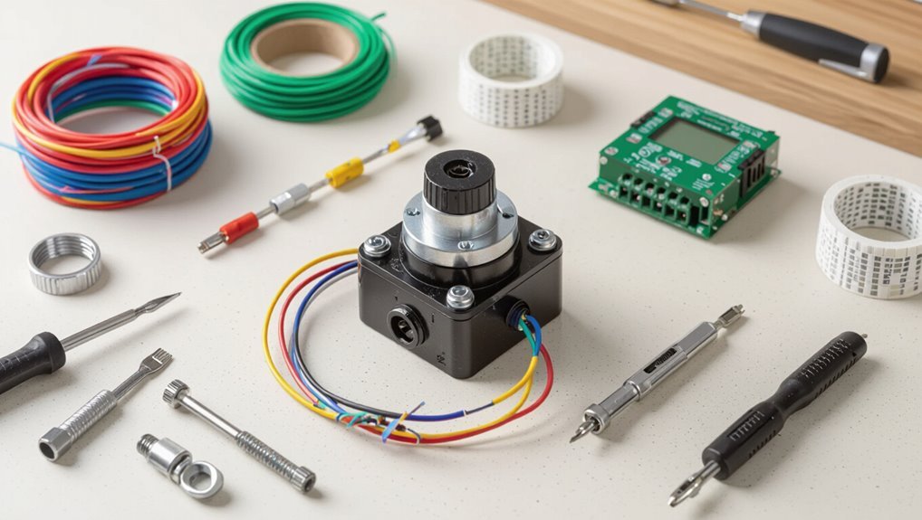
Wiring a sprinkler valve requires connecting the solenoid to the controller, routing low-voltage cable through zones, and ensuring proper grounding and waterproof connections.
Homeowners with basic electrical skills and simple single-zone or multi-zone systems can handle wiring, while complex setups, mains-voltage conversions, or unclear local codes warrant a professional.
Typical systems include single-station, multi-station (controller-driven), and master-valve or manifold configurations, each dictating slightly different wiring and valve layouts.
What wiring a sprinkler valve involves
Installing a sprinkler valve requires connecting a low-voltage control wire from the irrigation controller to the valve’s solenoid, securing the wiring against moisture, and ensuring proper electrical continuity and polarity for reliable operation.
The process covers routing and splicing waterproof connections, labeling and testing each zone, grounding considerations, and using correct wire gauge and connectors.
It explains how to wire sprinkler valve safely and effectively.
When you should attempt DIY wiring vs. call a professional
After outlining the components and steps involved in connecting a sprinkler valve to an irrigation controller, the next consideration is whether a homeowner should tackle the wiring themselves or hire a professional.
DIY is reasonable for simple, low-voltage, single-zone installs with basic tools and confidence.
Call a professional for complex multi-zone systems, buried or damaged wiring, unfamiliar electrical work, or local code and permit concerns.
Common sprinkler system types and valve configurations
Sprinkler systems come in several common layouts—single-zone, multi-zone, and master-valve setups—each dictating different valve arrangements and wiring patterns.
Single-zone systems use one valve and simple two-wire connections.
Multi-zone systems employ multiple valves controlled by a timer or controller, requiring individual common and zone wires.
Master-valve configurations add a primary valve wired in series for safety and flow control.
Tools, Materials, and Safety Precautions
A clear list of required tools and materials sets the foundation for safe and effective sprinkler valve wiring.
Essential electrical components and basic wiring terminology are introduced so readers can recognize parts and follow circuits correctly.
A concise safety checklist outlines precautions to take before beginning work, including power shutdown and appropriate personal protective equipment.
Required tools and materials
One set of common hand tools and a few specialty items will cover most sprinkler valve wiring jobs: wire strippers, a voltage tester, screwdriver set, waterproof wire connectors, low-voltage cable, and basic safety gear such as gloves and eye protection.
Necessary items include:
- Wire strippers and cutters
- Voltage tester or multimeter
- Waterproof connectors and heat-shrink tubing
- Low-voltage landscape cable and spare valve solenoids
Electrical components and wiring terminology beginners must know
Having gathered the basic tools and materials, the next focus is on the electrical components and wiring terminology beginners need to understand before making any connections.
Key components include the solenoid valve, controller/clock, transformer, zone wiring, common and hot wires, and terminal strip.
Terms: voltage (usually 24VAC), impedance, polarity, splice, waterproof connectors, and multimeter basics for testing continuity and voltage.
Safety checklist before starting work
Begin by assembling all required tools and personal protective equipment, and then verify that the work area is de-energized and free of hazards.
Confirm circuit breakers are off and locked, use a voltage tester, and ground as needed.
Gather insulated screwdrivers, wire strippers, connectors, and spare wire.
Wear safety glasses, gloves, and durable footwear.
Keep a first-aid kit and emergency contact information nearby.
Understanding Your Sprinkler Valve and Controller
The sprinkler valve consists of a solenoid with a common wire, individual zone wires, and a grounding conductor that complete the circuit.
Valve bodies and controllers typically mark terminals and use consistent wire colors to distinguish common from zone leads.
The controller sends a timed low-voltage electrical signal to a zone wire while the common returns current to activate the solenoid.
Valve anatomy: solenoid, common wire, zone wires, and ground
A sprinkler valve contains a solenoid that converts electrical signals from the controller into mechanical motion.
The solenoid mounts on the valve body and links to a diaphragm or plunger, opening water flow when energized.
The common wire returns current from all valves to the controller; individual zone wires carry control signals.
A ground provides safety and noise reduction where required.
Identifying valve terminals and wire colors
When preparing to connect a sprinkler valve to a controller, identify the solenoid’s two screw terminals—one for the zone (hot) wire and one for the common—then match those to the controller’s corresponding zone output and common terminal.
Typically, zone wires are colored red, blue, yellow or green; the common is usually white or black.
Confirm with a multimeter and label wires before final connection.
How controllers send signals to valves
Controllers send an electrical pulse to a valve solenoid to open or close it, with the controller completing a circuit between a specific zone output (hot) and the common terminal.
The pulse energizes the solenoid coil, shifting a plunger that changes diaphragm pressure and allows flow. Duration and sequence are controlled by program settings; voltage is typically 24VAC and wiring must maintain polarity and secure connections.
Preparing the Site and Existing Wiring
The technician first locates the valve box and controller to establish the work area and access points.
Existing wiring is inspected for frays, breaks, or corrosion that could affect connections.
Wire runs are then planned and conduit or burial depth selected to protect cables and meet local code.
Locating the valve box and controller
Before any wiring begins, identify the valve box and controller locations to guarantee accessible routing, adequate clearance, and compatibility with existing conduit or cable paths.
Map valve positions relative to zones, noting depth and proximity to irrigation lines.
Verify controller placement near power source and weather protection.
Plan conduit runs minimizing bends, avoiding obstacles, and allowing future access for maintenance and expansion.
Inspecting existing wiring for damage or corrosion
Inspect the existing wiring visually and electrically to identify frayed insulation, exposed conductors, brittle jacketing, green or white corrosion on terminals, and any moisture intrusion in splices or conduit.
Note loose or overheated connections, intermittent continuity, and increased resistance with a multimeter.
Document damaged segments, label circuits, and plan for replacement or repair of corroded terminals, compromised jacket sections, or wet splice locations before proceeding.
Planning wire runs and choosing conduit or burial depth
Plan wire routes with clear attention to accessibility, local code requirements, and future maintenance needs.
The installer selects direct paths avoiding roots, driveways, and utility lines, marks routes, and verifies depth requirements.
Choose conduit where mechanical protection or shallow burial conflicts exist; otherwise use direct-bury cable at code-specified depths.
Include pull boxes at bends and valve locations for easier repairs and expansions.
Step-by-Step Wiring Guide
The guide proceeds through a clear sequence of practical actions to complete the valve wiring.
It begins with powering off the controller and verifying power is removed, then moves on to stripping and preparing wires for safe handling.
Next, it covers attaching the shared common wire to all valves, connecting each zone wire to its respective solenoid, and securing every splice with wire nuts, waterproof connectors, or gel-filled caps.
Step 1 Power off the controller and verify power is off
Shut off power to the irrigation controller at the main breaker before beginning any wiring work and confirm the controller is de-energized.
A qualified person should lock out or tag the breaker.
Use a non-contact voltage tester on controller terminals and nearby wires to verify zero voltage.
Only proceed after confirming absence of power and documenting the breaker position to prevent accidental re-energization.
Step 2 Strip and prepare wires safely
Begin by selecting the correct tools and wire lengths for each station. Then cut, strip, and label conductors so connections are reliable and identifiable.
Use a quality wire stripper to remove insulation without nicking conductors. Trim frayed strands, twist and tin if appropriate, and apply heat-shrink tubing or waterproof connector boots.
Keep wire runs neat, leave service loops, and verify labels before proceeding.
Step 3 Connecting the common (shared) wire to all valves
With conductors stripped, labeled, and laid out, attention turns to routing and tying the common conductor that every valve will share.
The installer runs the common from the controller to each valve box, securing it along the trench.
At each valve, the common is connected to the solenoid common terminal or splice, using waterproof connectors and heat-shrink or tape for reliable, corrosion-resistant joints.
Step 4 Connecting individual zone wires to each valve solenoid
Attach each zone conductor to its corresponding solenoid terminal, ensuring correct polarity and secure, waterproof connections.
Match labels or controller zone numbers to valves, trim insulation back minimally, and slide conductors under the terminal screws or into push-fit clamps.
Verify tight mechanical contact and test continuity to confirm each zone responds independently before burying or closing valve boxes.
Step 5 Securing connections with wire nuts, waterproof connectors, or gel-filled connectors
Secure the spliced leads using appropriate connectors to protect against moisture, corrosion, and accidental disconnection.
Use twist-on wire nuts for indoor, dry splices; choose waterproof butt connectors or gel-filled wire caps for buried or exposed joints.
Strip properly, twist conductors, insert into the chosen connector, and crimp or tighten per manufacturer instructions.
Inspect and snug all connections before burial or enclosure.
Step 6 Running wires to the controller and labeling each zone
Begin routing the cable from each valve box toward the irrigation controller, keeping runs as direct as possible to minimize length and potential signal loss.
Pull cables neatly into the controller enclosure, separate conductors for common and zone wires, secure with staples or clips, and leave service loops.
Label each cable and corresponding terminal with durable tags or heat-shrink labels to match zone numbers for future maintenance.
Step 7 Restoring power and performing an initial test of each zone
Power is restored only after a final visual check confirms all wire connections are tight, insulation is intact, and valve boxes are closed.
Then the controller is energized and set to manual or test mode to activate each zone individually for inspection.
Each zone is observed for correct valve response, leaks, proper spray patterns, and pressure.
Faults are noted, power is cut, and corrections made before retesting.
Wiring Variations and Special Situations
The section addresses wiring variations and special situations commonly encountered in irrigation systems.
It outlines procedures for adding a master valve or pump-start relay, compares series versus parallel valve wiring, and covers low-voltage transformer placement and wiring.
It also explains how to connect multiple controllers or integrate smart controllers while maintaining proper isolation and voltage.
Wiring a master valve or pump-start relay
Several irrigation systems require a master valve or pump-start relay to control water supply and protect against pressure loss or backflow.
These devices are wired differently than individual zone valves and must be integrated into the controller’s common and zone circuits correctly.
The master valve or relay typically connects to a dedicated controller output, sharing the common wire.
Confirm proper voltage, use a diode or relay as specified, and follow local codes.
Series vs. parallel valve wiring considerations
When deciding between series and parallel wiring for irrigation valves, installers must weigh reliability, diagnostic clarity, and controller capacity:
Series wiring (daisy-chained controllers/relays) can simplify wiring runs but risks single-point failures and complicates troubleshooting.
Parallel wiring isolates circuits, easing diagnosis and allowing independent valve control, though it requires more conductor runs and controller zones.
Choose based on site layout, failure tolerance, and future expansion.
Low-voltage transformer placement and wiring
Proper placement and wiring of the low-voltage transformer greatly affect system reliability and safety, especially in complex or remote installations.
The transformer should be mounted in a dry, ventilated location near the controller, protected from weather, and on a dedicated circuit.
Use correctly gauged multi-conductor cable, maintain polarity, secure connections with waterproof connectors, and ground per local code to prevent voltage drop and faults.
Connecting multiple controllers or smart controllers
Having secured the transformer and routed main wiring, attention turns to configurations involving multiple controllers or modern smart controllers.
Multiple controllers require isolated common and dedicated zone leads or a relay interface to prevent signal conflict.
Smart controllers may share the transformer if rated, or use separate power modules.
Confirm common grounding, program coordination to avoid overlap, and follow manufacturer wiring diagrams for compatibility.
Troubleshooting Common Wiring Problems
When a zone fails to activate, the guide outlines concise diagnostic steps to isolate controller, wiring, and valve issues.
It also covers locating short circuits or blown fuses, tracing intermittent operation to loose or damaged connections, and identifying corroded wires or water-damaged splices.
Practical checks and simple fixes are presented so common faults can be found and repaired quickly.
Zone not activating: diagnostic steps
A non-activating zone is most often caused by wiring or controller faults and can be isolated through a few systematic checks.
First, confirm the controller sends signal by manually activating the station.
Next, verify continuity from controller to valve with a multimeter and inspect connectors for corrosion or loose wires.
Finally, test the valve solenoid by applying 24VAC directly to confirm valve function.
Short circuits and blown fuses: how to find and fix
Detecting short circuits and addressing blown fuses requires a systematic approach that isolates the fault while minimizing further damage.
Technicians should power down, inspect visible wiring for chafing, and use a multimeter to check continuity and resistance.
Disconnect zone wires one at a time to pinpoint shorts.
Replace blown fuses with correct ratings and repair or replace damaged wire insulation before restoring power and testing.
Intermittent operation and poor connections
Intermittent valve cycling and unreliable station activation often stem from poor electrical connections, corroded terminals, or loose wire nuts that introduce resistance and intermittent continuity.
Technicians should inspect terminal screws, re-strip and reseat conductors, tighten connectors, and replace damaged caps.
Use a multimeter to check voltage under load and wiggle-test joints.
Secure splices with rated connectors and protect exposed wiring from vibration and strain.
Corroded wires or water-damaged splices
Loose or corroded connections often lead to intermittent cycling, but prolonged exposure to moisture produces its own set of failures: corroded conductors and water-damaged splices that raise resistance, cause open circuits, or short adjacent wires.
Inspect insulation for green/white corrosion, cut back to clean copper, re-twist, solder or use heat-shrink butt connectors rated for underground use, then seal with silicone and test.
Testing, Calibration, and Final Checks
A complete system test verifies each zone’s coverage and uncovers leaks or misaligned heads before finalizing the wiring.
The technician should measure solenoid resistance with a multimeter, adjust controller settings and run times to match watering needs, and confirm valves respond reliably.
Finally, weatherproofing and securing the valve box guarantee long-term protection and safe operation.
How to run a full system test and verify coverage
Begin by activating each zone one at a time from the controller to observe valve operation, spray patterns, and nozzle alignment under normal pressure. This controlled run-through lets the installer identify misdirected heads, coverage gaps, overspray onto sidewalks or structures, and any valves that fail to open or close properly.
Adjust head angles, swap nozzles, trim vegetation, and reposition sprinklers as needed. Repeat until uniform coverage is achieved.
Checking solenoid resistance with a multimeter
Use a multimeter to measure each solenoid’s coil resistance to confirm proper operation before completing the system.
Disconnect power, remove solenoid leads, set meter to ohms, and probe coil terminals.
Compare readings to manufacturer specifications (typically 20–200 ohms).
Replace solenoids showing open circuits or markedly out-of-range values.
Reconnect wiring and retest continuity after replacement to guarantee reliable valve activation.
Adjusting controller settings and run times
With solenoids verified and continuity restored, attention shifts to programming the controller and setting run times to match actual irrigation needs.
Zones are tested individually, adjusting durations for soil type, plant needs, and sprinkler coverage.
Seasonal schedules, start times, and cycle-soak options are configured to prevent runoff.
Runoff and uniformity checks validate settings; final adjustments optimize water use and plant health.
Weatherproofing and securing the valve box
Several simple steps guarantee the valve box remains weatherproof and secure: sealing cable entries, anchoring the box against shifting, and protecting solenoids and wiring from moisture and pests.
Use silicone or foam grommets on conduits, elevate components on a small platform, apply dielectric grease to connectors, and install rodent barriers.
Verify lids fit snugly and fasten with corrosion-resistant screws to prevent movement and intrusion.
Maintenance Tips and Recommended Schedule
The article now outlines practical maintenance tips and a recommended schedule for wiring care, starting with seasonal checks and winterization steps to protect connections and conduit.
It then emphasizes routine inspections to detect corrosion, loose terminals, or insulation damage that can lead to wiring failures.
Finally, clear criteria are given for when solenoids should be replaced or a valve rewired to restore reliable operation.
Seasonal checks and winterization wiring steps
Begin seasonal checks at least twice a year—spring startup and fall winterization—to verify wiring integrity, controller programming, and valve operation before temperature extremes.
During fall, isolate and drain exposed valve wiring, remove batteries, and set controller to freeze mode or turn power off as local practice dictates.
Label buried splices, inspect conduit for cracks, and schedule corrective repairs before freezing weather arrives.
Routine inspections to prevent wiring failures
One clear inspection routine performed quarterly helps catch loose connections, corrosion, and insulation damage before they cause failures.
Technicians evaluate junctions, conduit, and controller terminals, documenting findings and scheduling minor repairs.
Recommended actions include:
- Check terminal tightness and wire strain relief
- Inspect for moisture, corrosion, and frayed insulation
- Test continuity and voltage under load
- Clean and protect contacts with dielectric grease
When to replace solenoids or rewire a valve
Replace solenoids or rewire a valve when measurable performance decline, recurring electrical faults, or visible damage indicate the root cause is component failure rather than a temporary connection issue.
Replace solenoids every 3–7 years depending on water quality and usage; rewire when insulation, corrosion, or intermittent operation persists after cleaning.
Prioritize failed solenoids, burnt coils, frayed leads, or persistent shorts.
Cost, Time Estimates, and When to Hire a Pro
Typical DIY wiring of a single sprinkler valve generally takes one to two hours and involves modest material costs for wire, connectors, and a timer.
Homeowners should consider a licensed irrigation electrician if local code compliance, buried power lines, complex multi-zone systems, or persistent electrical faults are present.
When contacting contractors, ask about licensing and insurance, experience with irrigation systems, a written estimate, and warranty terms.
Typical DIY time and material cost breakdown
A basic backyard sprinkler valve installation usually takes a DIYer between 1 and 3 hours and requires a modest set of materials—valve, wire, connectors, and basic tools—costing roughly $30–$100 for parts. Typical breakdowns list time, parts, and difficulty; total cost varies by quality.
| Item | Time | Cost |
|---|---|---|
| Valve wiring | 1–3 hr | $30–$100 |
| Extra wire | 0.5 hr | $5–$20 |
Signs you should hire a licensed irrigation electrician
When should a homeowner call a licensed irrigation electrician?
Complex systems, multiple zones, or faulty wiring that trips breakers justify professional help.
Expect labor costs and permit fees; small repairs may take an hour, rewiring or controller relocation several hours to a day.
Hire a pro for unclear wiring, shared circuits, code compliance, or lack of time, tools, or confidence to guarantee safety and reliability.
Questions to ask contractors before hiring
How much will it cost, and how long will it take—these are the essential queries a homeowner should pose to any contractor bidding on irrigation work.
Additional focused questions clarify scope, guarantees, and when to escalate to a professional electrician.
- Request a written estimate and payment schedule
- Ask for start and completion dates
- Verify licensing and insurance
- Define warranty and response time for issues
Conclusion
Successfully wiring a sprinkler valve guarantees efficient irrigation and long equipment life when proper planning and safety are observed. For example, a homeowner in Tucson rewired a malfunctioning zone by replacing corroded splices, confirming continuity to the controller, and securing waterproof connectors—restoring scheduled watering without professional help. Following the outlined steps, testing procedures, and routine maintenance prevents common failures; if problems persist or complex irrigation systems are involved, consulting a licensed irrigation technician is advisable.
