How to Install a Grease Trap: Step-by-Step Guide for DIY & Contractors
To install a grease trap effectively, first understand that it captures fats, oils, and grease before they enter sewer lines. Key steps include selecting the right size based on flow rate, positioning it between fixtures and the sewer line, ensuring proper slope, and venting. For in-ground interceptors, you’ll need to excavate, create a stable bedding, align pipes accurately, and backfill correctly. Under-sink units require proper fittings and slope for optimal performance. Always test for leaks, document the installation, and schedule regular cleanings to prevent issues. For detailed procedures, troubleshooting tips, and compliance guidance, continue reading.
What a Grease Trap Is and Why Proper Installation Matters
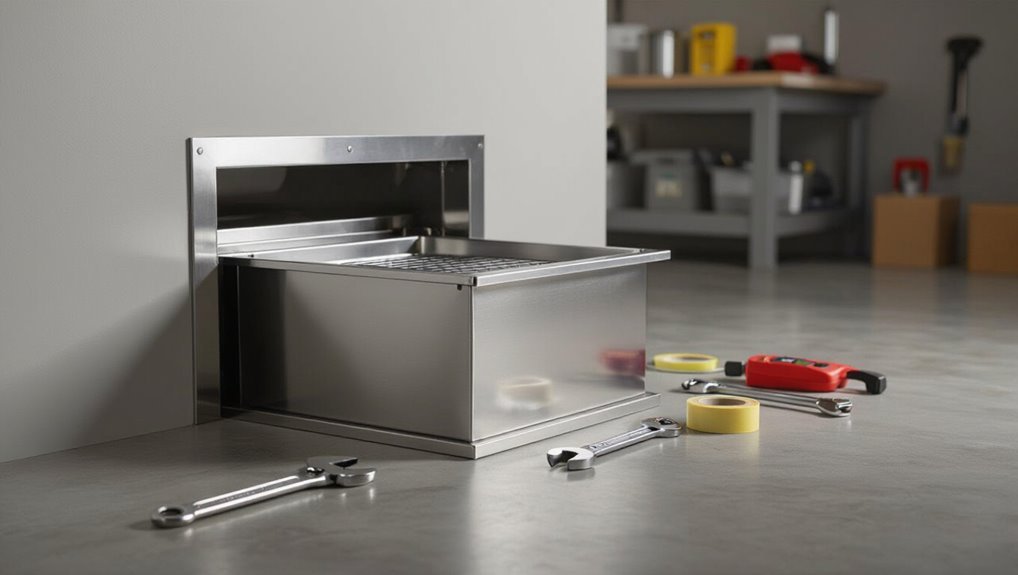
A grease trap is a plumbing device that captures fats, oils, and grease (FOG) from wastewater to prevent blockages and protect sewer systems.
Proper installation is essential for health, plumbing integrity, and compliance with local regulations, as incorrect sizing or placement can lead to overflows, backups, and fines.
These units are commonly required in commercial kitchens and some multi-unit residential buildings, while most single-family homes use smaller-scale solutions.
Definition and purpose of grease traps
Grease traps are plumbing devices installed between kitchen fixtures and the sewer to capture fats, oils, and grease (FOG) before they enter the wastewater system.
They separate and retain buoyant FOG while allowing water to flow, preventing pipe blockages and municipal system strain.
Clear understanding of function informs selection, placement, sizing, and how to install a grease trap to guarantee effective long-term operation.
Health, plumbing, and regulatory reasons to install correctly
When installed and maintained correctly, grease traps protect public health, preserve plumbing integrity, and secure compliance with local regulations by preventing fats, oils, and grease from entering sewage systems, attracting pests, and causing sanitary hazards.
Proper installation reduces blockages, costly backups, and pipe corrosion, minimizes sewer overflows and environmental contamination, and guarantees inspections, permits, and fines are managed through documented, code-compliant practices and routine maintenance.
Typical locations where grease traps are required (residential vs commercial)
Although regulations vary by jurisdiction and designated use, grease traps are most commonly mandated in commercial kitchens and certain multiunit or high-usage residential settings.
Required locations include restaurants, cafeterias, food trucks, catering facilities, nursing homes, and apartment complexes with shared kitchens.
Single-family homes typically do not require traps unless local codes or high grease output justify installation.
Compliance depends on local plumbing authority.
How to Choose the Right Grease Trap
Selecting the appropriate grease trap requires matching unit size to kitchen flow rate, desired retention time, and expected grease capacity.
Choice of type—passive, automatic, or interceptor—and materials such as plastic, concrete, or steel affect performance, maintenance, and installation constraints.
Local codes, permit requirements, and manufacturer specifications must be verified before final selection.
Sizing a grease trap: flow rate, retention time, and grease capacity
Proper sizing of a grease trap depends on three core variables: the facility’s peak flow rate, the required retention time to let grease rise, and the unit’s grease storage capacity before maintenance is needed.
Calculate peak flow from simultaneous fixtures, apply local retention standards (often 30–60 minutes), and guarantee storage accommodates expected grease load between cleanings.
Verify calculations against plumbing codes and adjust for future demand.
Types of grease traps (passive/automatic/interceptor)
Sizing determines the performance requirements for a grease control system, but choosing the right type of trap also affects installation, maintenance, and long-term cost.
Passive units are simple, low-cost, and require frequent manual cleaning.
Automatic (mechanical) units pump out separated grease, reduce labor, and have a higher upfront expense.
Interceptors handle large flows and sit externally for heavy commercial use.
- Passive
- Automatic
- Interceptor
Materials and construction options (plastic, concrete, steel)
Material choice—plastic, concrete, or steel—directly influences durability, installation method, maintenance needs, and lifecycle cost.
Plastic offers corrosion resistance, light weight, and easier handling but lower impact strength.
Concrete provides longevity, thermal mass, and heavy-duty performance at higher installation effort.
Steel delivers high strength and compact sizing yet requires corrosion protection and regular inspection to prevent premature failure.
Local codes, permits, and manufacturer specifications to check
Before selecting a grease trap, the installer should verify local plumbing and wastewater codes, obtain any required permits, and review the manufacturer’s installation and maintenance specifications to guarantee compliance.
Confirm required capacity, interceptor type, setback distances, access/venting, and sampling provisions.
Check materials approval, anchor and load limits, testing and certification, recommended flow rates, warranty conditions, and approved service intervals before purchase and installation.
Pre-Installation Planning and Site Preparation
Before beginning work, the installer verifies pipe layout, flow direction, and the ideal placement for the grease trap while measuring and marking the installation area.
They locate utilities and underground hazards, assemble required tools, materials, and safety equipment, and confirm any permits needed.
Finally, they schedule inspections and coordinate timing to minimize disruption.
Assessing pipe layout, flow direction, and ideal placement
A clear survey of existing plumbing is the first step in determining where a grease trap should be installed.
Inspect pipe routes, junctions, and slope to confirm gravity flow toward the trap. Identify primary grease-producing fixtures and guarantee accessibility for servicing.
Avoid locations that impede workflow, violate codes, or require excessive rerouting. Prioritize shortest, downhill run between fixtures and trap.
Measuring and marking the installation area
Measure the footprint and clearances for the grease trap and surrounding access paths, recording exact floor elevations, wall distances, and pipe centerlines to guarantee proper fit and slope.
Then outline trap edges, inlet/outlet locations, and service access on the floor with durable markers.
Verify clearances for lids and maintenance equipment, note obstruction positions, and create a scaled sketch with measured dimensions for installers.
Utilities and underground hazards to locate before digging
Locate all underground utilities and hazards prior to excavation to prevent service interruptions, costly repairs, and safety risks.
Contact local utility locating services and obtain markouts for gas, water, sewer, electrical, telecom, and fiber.
Inspect for septic lines, irrigation, and buried fuel tanks.
Review site maps, permit requirements, and notify adjacent property owners.
Document markings and plan safe excavation boundaries before digging.
Required tools, materials, and safety equipment
Several specific tools, materials, and safety items are essential before beginning grease trap installation to guarantee efficiency and compliance.
Required items include durable pump and plumbing tools, approved trap components, and PPE.
Suggested checklist:
- Heavy‑duty wrenches, pipe cutters, and a submersible pump
- Grease trap unit, seals, fittings, and approved sealant
- Gloves, eye protection, respirator, and safety boots
Obtaining permits and scheduling inspections
Begin the permitting process early to confirm local regulations, secure required permits, and coordinate inspections with municipal authorities; failure to do so can delay installation or require costly rework.
The installer should submit accurate plans, verify grease trap sizing and backflow prevention requirements, pay fees, and schedule pre- and post-install inspections.
Maintain documentation, comply with inspection feedback, and obtain final approval before operation.
Step-by-Step Installation for In-Ground Grease Interceptors
The installation begins with excavating a pit to the specified depth, creating a level base and appropriate bedding for the interceptor.
The unit is set in place, checked for slope and alignment, and tied into inlet and outlet piping with required traps, tees, and venting before access covers, risers, and grade seals are fitted.
Final work includes systematic backfilling, compaction, and surface restoration to manufacturer and code specifications.
Excavate and prepare the pit: depth, base leveling, and bedding
Excavate to the specified dimensions and depth so the interceptor sits on undisturbed soil with its inlet and outlet aligning to the building’s piping; depth should allow for a minimum burial cover per manufacturer and local code while leaving room for a compacted bedding layer.
Remove loose material, confirm stable subgrade, and install a leveled, well-compacted granular bedding (sand, pea gravel, or crushed stone) to manufacturer thickness tolerances.
Set interceptor into position and check slope and alignment
Set the interceptor into the prepared bedding using appropriate lifting gear, centering it so inlet and outlet orientations match the building piping while maintaining the manufacturer’s required clearance from walls and other structures.
Verify unit sits level laterally, then confirm outlet invert slope meets specified gradient toward downstream sewer.
Adjust bedding to correct pitch and rotation.
Recheck clearances and final alignment before backfilling.
Connect inlet and outlet piping: traps, tees, and venting
Begin by preparing all inlet and outlet connections to validate a secure, code-compliant hydraulic path between the building plumbing and the interceptor.
Install appropriate inlet traps and flow-control tees to prevent backflow and allow baffle dispersion.
Size and slope piping per code, use approved materials and fittings, provide cleanouts, and connect venting as required to guarantee proper flow, trap seal protection, and maintenance access.
Install access covers, risers, and sealing to grade
Installers align access covers and risers so the interceptor’s openings sit flush with final grade, ensuring watertight seals and safe, code-compliant access for inspection and maintenance.
Riser sections are trimmed to height, gasketed joints torqued, and covers tested for smooth operation. Non-shrink sealant or approved collars seal annular space.
Covers are locked or bolted per local code to prevent unauthorized entry.
Backfill, compact, and restore surface
After access covers and risers are secured, backfill around the interceptor using specified materials in controlled lifts to protect the unit and adjacent piping.
Compact each lift to manufacturer density requirements, monitor for settlement, and maintain alignment.
Restore surfacing to match surrounding grade and drainage.
Reinstall pavement, sod, or landscaping per local codes, verify final elevations, and document as-built conditions for maintenance records.
Step-by-Step Installation for Under-Sink or Inline Grease Traps
The technician begins by disconnecting the sink drain and measuring the space to determine ideal placement and mounting—wall-mounted or floor-standing.
Plumbing connections follow, with attention to proper fittings, P-trap alignment, venting, and achieving the correct slope.
Once secured, the unit is pressure-tested and inspected for leaks before final commissioning.
Disconnect sink drain and measure for placement
Disconnecting the sink drain and measuring for placement begins by shutting off the water and clearing the space beneath the sink so the piping and hanger hardware are accessible; this guarantees accurate measurements and safe work.
The installer disconnects trap and tailpiece, inspects pipe alignment, and measures distance to the desired grease trap inlet, accounting for tubing, fittings, and required slope before finalizing location and marking mounting points.
Mounting options: wall-mounted vs floor-standing
Which mounting option best suits the space and workflow depends on available clearance, floor strength, and service access.
Wall-mounted units save floor area and simplify cleaning beneath but require sturdy wall framing and secure anchors.
Floor-standing traps handle heavier capacities, resist vibration, and allow easier relocation but need adequate floor load capacity and unobstructed service access for inspection and removal.
Connect plumbing: fittings, P-trap alignment, and venting
Begin by laying out all needed fittings and confirming inlet/outlet orientations to guarantee a straight, short run between the sink drain, grease trap, and the building sanitary line.
Install appropriate reducers, adapters, and cleanouts. Align and set the P-trap to maintain seal height and prevent siphoning.
Connect venting per code to avoid slow drainage and odors, using approved fittings and supports.
Secure unit, test for leaks, and ensure proper slope
With the plumbing aligned and P-trap set, the grease trap is positioned and fastened to prevent movement during use and servicing.
All fittings are tightened, seals inspected, and test water introduced to check for leaks.
Drain slope is verified (typically 1/4″ per foot) from fixtures to trap; adjustments are made with shims or pipe rework.
Final inspection confirms stability and watertight connections.
Installation Details Common to All Grease Traps
Proper installation requires attention to shared details that affect performance and serviceability. These include correct slope and flow direction, proper venting and odor control, and accessible manways or cleanouts for maintenance.
Installers should also position baffles, filters, and any automatic skimmers per manufacturer specifications to guarantee effective separation and ease of upkeep.
Ensuring correct slope and flow direction
Slope and flow direction determine whether wastewater enters, slows, and exits the grease trap as planned; installers must set inlet and outlet piping to maintain a consistent fall that prevents standing water or excessive velocity.
Piping grade typically follows local code, commonly 1/4″ to 1/8″ per foot. Align inlet above baffle and outlet at designed elevation, verify with level and test flow before backfilling.
Venting requirements and odor control
After setting inlet and outlet elevations to establish correct flow, attention turns to venting and odor control to protect indoor air quality and system performance.
Proper venting prevents siphoning, equalizes pressure, and allows volatile gases to escape above roofline per code.
Add biological or enzyme treatments, install sealed covers and carbon filters where needed, and guarantee vent sizing and termination follow local regulations.
Access for maintenance: manways and cleanout placement
Provide clear, safe access points to guarantee routine inspection, cleaning, and repairs can be performed without disrupting kitchen operations.
Manways should be sized and located for human entry or adequate reach, labeled, and secured with gas-tight covers.
Cleanouts and sampling ports must be accessible at floor level, unobstructed, and positioned for pump truck access.
Allow service clearance per local codes for safe maintenance.
Installing baffles, filters, and automatic skimmers if applicable
Install internal components in a sequence that guarantees correct hydraulic flow and easy future servicing: secure inlet and outlet baffles to their designed elevations to control velocity and promote grease separation.
Fit filters or screens to trap solids ahead of the main chamber, and, where specified, position automatic skimmers at the appropriate liquid level with accessible power and control connections.
Verify seals, alignments, and removable access for routine cleaning.
Testing, Commissioning, and Final Inspection
Testing and commissioning verify that the grease trap is watertight and that inlet and outlet flows meet design rates through prescribed leak and flow tests.
Proper documentation of test results, as-built diagrams, and manufacturer paperwork is required for permits and final inspections.
Inspectors typically check trap orientation, access/cover seals, inlet/outlet piping, flow control devices, and compliance with local codes on the inspection checklist.
Leak testing and flow testing procedures
Begin by verifying that all fittings, seals, access covers, and discharge lines are secured and that the grease trap is free of debris before initiating leak and flow tests.
Perform a static leak test by filling to operational level and inspecting joints for seepage.
Conduct a flow test using measured water at design flow, confirming retention time, discharge rate, and absence of bypass or surging.
How to document installation for permits and inspections
Document the installation thoroughly to satisfy permit requirements and streamline final inspection: record as-built conditions, component serial numbers, materials, deviation notes, and the dates and results of all leak, flow, and commissioning tests.
Provide labeled drawings, photo evidence of key connections, manufacturer manuals, warranty forms, and calibration certificates.
Include signed technician checklists, permit application copies, and a concise commissioning report with corrective actions and completion dates.
Common inspection checklist items inspectors look for
Having completed thorough documentation for permits and commissioning, the installer should prepare for the specific items inspectors routinely verify during testing, commissioning, and final inspection.
Inspectors focus on functional performance, regulatory compliance, and safety.
- Proper grease trap sizing, inlet/outlet elevations, and flow rate verification
- Secure venting, access covers, and labeling per code
- Leak-free joints, operational baffles, and maintenance access clarity
Initial Startup and Best Startup Practices
The initial startup focuses on flushing and priming the trap to guarantee correct flow and sealing.
Technicians should record baseline measurements and take photos for future reference.
Clear instructions on routine operation and maintenance must be communicated to staff or homeowners.
Flushing and priming the trap
Begin by flushing the grease trap with clean water to remove loose debris and confirm unobstructed flow through inlet and outlet lines.
Then prime the unit by filling to the recommended operating level, ensuring baffles and seals are submerged.
Verify no air pockets remain, test flow rate with a controlled water volume, and check for immediate leaks or unusual noises before regular service begins.
Record initial measurements and photos
Record initial measurements and capture clear photos of the grease trap and its connected piping before leaving the site.
Document inlet/outlet elevations, pipe diameters, baffle positions, and waterline height.
Photograph labeling, serial numbers, and clearance access.
Note date, installer name, and any deviations from plan.
Store files with the installation checklist for future inspections, maintenance, and warranty verification.
Communicating operation to staff or homeowners
Having documented measurements, photos, and installation details, the installer should now brief staff or homeowners on system operation and initial startup procedures.
The briefing covers purpose, flow limits, required water use during startup, initial maintenance schedule, waste disposal rules, and emergency contacts.
Provide concise written instructions, a simple checklist, and demonstrate sampling points and safe handling to guarantee consistent, compliant operation.
Maintenance, Cleaning, and Troubleshooting
A clear maintenance plan specifies service frequency based on trap capacity and kitchen load to prevent buildup and backups.
Cleaning follows a step-by-step routine: isolate flow, remove and scrape solids and grease, vacuum or pump out liquids, inspect baffles and seals, then disinfect and document the service.
Persistent odors, slow drains, or frequent overfills indicate a failing or undersized trap and require corrective actions such as increased cleaning frequency, repair or replacement, and proper disposal or recycling of removed grease through licensed haulers or rendering services.
Recommended maintenance schedule and capacities
Establishing a clear maintenance schedule and selecting the correct trap capacity are critical to reliable grease-trap performance.
Maintenance intervals depend on kitchen size, volume of FOG (fats, oils, grease) generated, and local regulations; typical service ranges from weekly to monthly.
Capacity should match peak flow and retention time requirements.
Document schedules, inspect regularly, and adjust frequency based on accumulation rates and compliance needs.
How to clean a grease trap step-by-step
Begin by shutting off any equipment that feeds wastewater into the grease trap and closing inlet and outlet valves to prevent flow during service.
Remove the lid, skim and scoop accumulated grease and solids into approved containers, inspect baffles and inlet/outlet for blockages, vacuum remaining slurry if needed, clean interior surfaces with non-corrosive detergent, rinse, reinstall lid, reopen valves, and record service details.
Signs of a failing or undersized grease trap and corrective actions
Detectable symptoms of a failing or undersized grease trap include slow drains, recurring clogs, strong sewage or rancid odors near fixtures, grease-slick effluent at the outlet, and unusually frequent need for pumping or cleaning.
Corrective actions: inspect baffles and inlet/outlet for blockages, verify trap capacity versus flow, increase pumping frequency temporarily, install flow restrictors or larger trap, and repair damaged seals or plumbing.
Safe disposal and recycling options for removed grease
When removed from a grease trap, fats, oils, and grease (FOG) must be handled as a managed waste stream to prevent sewer blockages, environmental harm, and regulatory violations.
This requires segregation, containment in labeled, leak-proof containers, and documentation of transfer for disposal or recycling.
Proper options include:
- Rendering or conversion to biofuel via licensed collectors.
- Composting or anaerobic digestion where permitted.
- Approved landfill disposal with manifest and receipts.
Common Installation Mistakes to Avoid
Many installations fail because of incorrect piping connections, insufficient slope, or improper unit sizing.
These mistakes commonly lead to odors, backups, and violations of local codes.
Clear guidance on correct pipe runs, slope standards, and capacity selection helps prevent operational and regulatory problems.
Typical DIY errors with piping, slope, and sizing
Although seemingly straightforward, DIY grease trap installation often falters because of incorrect piping choices, improper slope, and undersized units; these mistakes compromise flow, trap performance, and long-term maintenance.
Common errors include using wrong pipe materials or diameters, creating inadequate or excessive slopes that cause clogging or stagnation, and selecting traps based on guesswork rather than fixture units and peak flow calculations.
How to prevent odors, backups, and code violations
Preventing odors, backups, and code violations hinges on correct installation details and routine maintenance; even small lapses in venting, seals, or access can lead to persistent smells, slow drainage, and regulatory fines.
Inspect vents, guarantee proper slope, use gas-tight gaskets, secure covers, and install approved access risers.
Schedule regular pumping, document maintenance, and follow local codes to avoid citations and operational issues.
Cost Estimates and When to Hire a Professional
A concise cost overview helps owners budget for unit price, excavation, plumbing work, and permit fees.
Guidance should clarify when a contractor is advisable versus a feasible DIY project, and list key questions to vet bidders.
A simple checklist for comparing bids guarantees informed hiring decisions.
Typical cost breakdown: unit, excavation, plumbing, permits
Cost is a major consideration when planning grease trap installation, and it typically breaks down into four components: the unit, excavation or site prep, plumbing connections, and permits or inspections.
Unit cost varies by capacity and material.
Excavation includes labor and disposal.
Plumbing covers fittings, piping, and labor.
Permits and inspections add fees and time.
Obtain quotes to compare total projected costs.
When a contractor is recommended vs DIY feasibility
After assembling cost estimates for the unit, excavation, plumbing, and permits, the next decision is whether to hire a professional or attempt a DIY installation.
A contractor is recommended for complex sites, deep excavation, strict local codes, commercial systems, or when certified inspections are required.
DIY may suit simple residential installs, experienced homeowners, minimal trenching, and where permits allow owner-performed work.
Questions to ask a contractor and checklist for bids
How should prospective clients evaluate contractor bids to guarantee accurate pricing, proper permits, and reliable workmanship? Prospective clients should request itemized estimates, permit confirmation, insurance proof, timelines, references, and warranty details. Compare bids against a checklist, verify licenses, and prioritize clear communication.
| Concern | Response |
|---|---|
| Price transparency | |
| Permits | |
| Insurance | |
| Timeline | |
| References/warranty |
Real-World Examples and Case Scenarios
The article presents two concise case scenarios to illustrate practical considerations.
One describes a small restaurant retrofit with a step-by-step summary of assessment, pipe rerouting, trap selection, and testing.
The other outlines a residential basement or home-kitchen installation emphasizing space constraints, venting, and maintenance needs.
Small restaurant retrofit example with step summary
One practical retrofit involved a 35-seat neighborhood diner upgrading to an indoor grease trap to comply with municipal regulations and reduce plumbing backups.
Assessment identified flow rates, pipe routing, and space constraints.
Steps: select appropriately sized trap, shut main, cut and fit piping, install inlet/outlet baffles, secure venting, test for leaks, document installation and schedule regular cleaning.
Residential basement or home-kitchen installation example
Many homeowners converting a basement or updating a home kitchen encounter space, venting, and access limitations when adding a grease trap.
The example outlines site selection near the main drain, compact trap models, routing of vent and overflow, trap anchoring, and provision for periodic cleaning.
Compliance with local codes, noise control, and minimal disruption to existing plumbing are emphasized throughout the retrofit.
Manufacturer Resources and Further Reading
The article directs readers to manufacturer websites and technical portals for installation manuals, sizing calculators, and links to local plumbing and health code resources.
It notes manufacturer-recommended tools, sealants, and replacement parts that simplify installation and guarantee compliance.
Readers are encouraged to consult those resources before ordering equipment or beginning work.
Where to find installation manuals, sizing calculators, and local code resources
Where can installers and facility managers locate the specific documentation and tools needed for correct grease trap selection and installation?
Manufacturer websites host installation manuals, cut sheets, and sizing calculators.
Trade associations and plumbing suppliers provide guides and unit comparisons.
Municipal code offices and online building-code databases publish local grease control regulations and permit requirements.
Technical forums and certified rep contacts offer clarifications and updates.
Recommended tools and products for installation
Essential-tool lists and product references help installers assemble everything required for a correct grease trap installation, from excavation tools and levelers to pipe cutters, solvent weld kits, gaskets, and certified test plugs.
Manufacturer catalogs and spec sheets guide compatible fittings, while safety gear and testing kits guarantee compliance.
- Pipe cutters, solvent, gaskets
- Leveling tools, shims, anchors
- Test plugs, seals, safety PPE
Conclusion
Proper installation of a grease trap guarantees compliance, prevents costly clogs, and protects plumbing and the environment. Whether selecting an in-ground interceptor or an under-sink unit, careful planning, correct sizing, and adherence to local codes are essential; otherwise, premature failure and fines may follow. When should one risk poor installation and its consequences instead of investing time or professional help to get it right? Ultimately, the right choice saves money, downtime, and headaches.