How Does a Flow Regulator Work? Simple Explanation, Types, and Common Uses
A flow regulator ensures a consistent liquid or gas flow rate by automatically adjusting an internal orifice or valve in response to pressure changes. It utilizes components like springs, diaphragms, or sensing chambers to regulate flow effectively, and often includes check valves to prevent backflow. Flow regulators come in various types, including fixed orifices, pressure-compensating units, manual needle valves, and electronic regulators. They’re commonly used in plumbing, HVAC systems, medical devices, irrigation, and industrial applications. Further sections will cover types, selection criteria, and installation tips.
What a Flow Regulator Is and Why It Matters
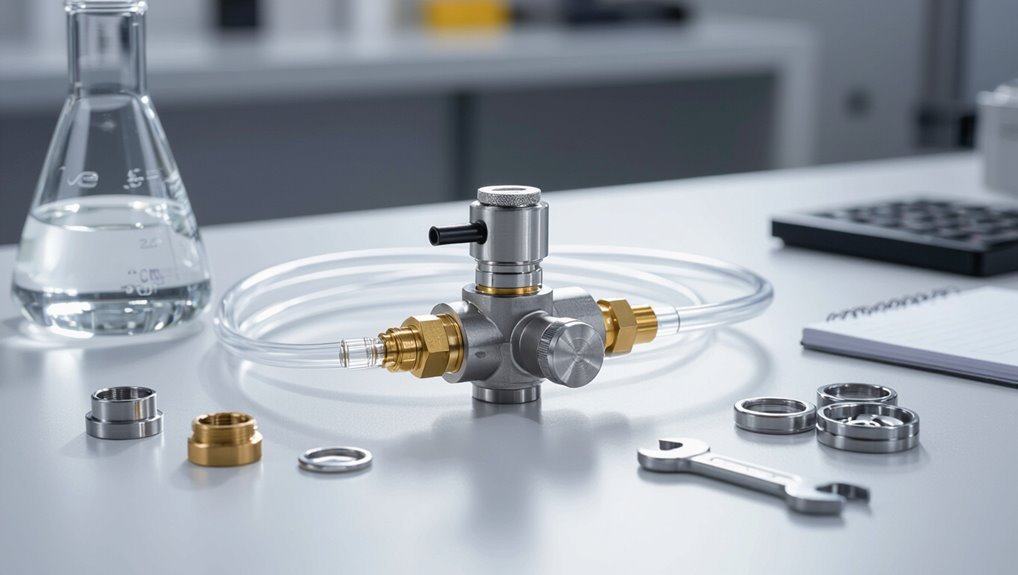
A flow regulator is a device that maintains a set fluid flow rate by constricting or redirecting the passage of liquid or gas.
Its primary functions include stabilizing system performance, preventing overpressure or underflow, and improving efficiency and safety.
These devices are used across industries such as plumbing, HVAC, chemical processing, medical devices, and irrigation where consistent flow control is essential.
Clear definition of a flow regulator
Flow regulators are mechanical or electronic devices designed to maintain a controlled, consistent rate of fluid or gas flow through a system despite variations in pressure, temperature, or demand.
A clear definition: a component that senses flow or pressure and adjusts or restricts passage to stabilize output.
Understanding how does a flow regulator work clarifies its role in predictable system performance and safety.
Primary functions and benefits in fluid systems
Regulates fluid movement to confirm consistent delivery and protect system components.
It maintains set flow rates despite pressure or demand changes, reduces wear and vibration, prevents overflow or cavitation, and assures accurate dosing.
Benefits include improved efficiency, prolonged equipment life, stable process control, reduced maintenance, and enhanced safety.
Predictable flows enable reliable system performance and simplified diagnostics.
Common industries and applications overview
Industries from manufacturing and chemical processing to water treatment and medical devices rely on flow regulators to guarantee precise fluid delivery under varying pressures and demands.
They appear in oil and gas metering, HVAC balancing, laboratory dosing, irrigation systems, food and beverage production, and automotive fuel and lubrication circuits.
Applications prioritize stability, safety, regulatory compliance, and cost-effective performance across steady and fluctuating operating conditions.
How Flow Regulators Work Simple, Step-by-Step Explanation
The explanation begins with the basic operating principles—how pressure, an orifice, and mechanical elements interact to set flow.
It then identifies internal components (valve seat, springs, diaphragms) and explains each role in controlling passage and response.
Finally, it shows how the regulator maintains steady flow as inlet pressure changes using a simple example to visualize the balancing actions.
Basic operating principles (pressure, orifice, and mechanical elements)
Several fundamental elements determine how a flow regulator maintains a steady flow: upstream pressure, a calibrated orifice, and mechanical components that respond to pressure changes.
The regulator balances inlet pressure against flow resistance through the orifice; mechanical elements (springs, diaphragms, valves) adjust orifice effective size to counter pressure fluctuations.
This dynamic equilibrium preserves consistent downstream flow despite varying supply conditions.
Internal components and their roles
A flow regulator contains a small set of interacting parts—an inlet and outlet body, a calibrated orifice, a sensing chamber with a diaphragm or piston, a spring or equivalent preload, and a control valve—that together sense pressure changes and translate them into precise adjustments of the effective flow area.
As inlet pressure rises, the sensing element shifts against the spring to reduce the valve opening, and when pressure drops, the spring repositions the valve to increase opening, maintaining a near-constant downstream flow.
The housing supports seals and guides; the orifice sets baseline flow; the sensing element detects differential pressure; the spring sets setpoint; the control valve modulates flow; seals prevent leakage; fasteners secure assembly for reliable operation.
How flow is maintained under changing pressure conditions
Although inlet pressure may fluctuate, the regulator continuously balances forces so downstream flow stays nearly constant: a sensing element detects pressure or flow changes, prompting a movable restriction to adjust aperture.
Spring and diaphragm forces oppose inlet variations, creating equilibrium. The result is rapid mechanical adjustment that compensates transient spikes or drops, preserving target flow rate despite upstream instability.
Visualizing flow regulation with a simple example
One simple way to visualize a flow regulator is to imagine a water line feeding a garden hose where a spring-loaded valve automatically narrows or widens its opening to keep the hose output steady.
As inlet pressure rises, the valve closes slightly, and as pressure falls, it opens, with a diaphragm sensing downstream pressure and the spring providing the opposing force that establishes a new balance.
The regulator continuously adjusts orifice size to maintain set flow despite supply fluctuations.
Main Types of Flow Regulators and How They Differ
The main types of flow regulators are distinguished by their mechanism of control, application scope, and response to pressure changes. Typical categories include fixed-orifice, pressure-compensating, needle/globe, electronic/motorized, and integrated check-valve designs, each offering trade-offs in precision, adaptability, and complexity.
The following list highlights four key considerations when selecting among these types.
- Control precision versus simplicity
- Pressure sensitivity and compensation
- Suitability for automated or manual operation
- Anti-backflow and safety integration
Fixed-orifice regulators
Fixed-orifice regulators provide a simple, cost-effective method of controlling flow by using a precisely sized opening that remains constant regardless of downstream conditions.
They deliver predictable flow rates when upstream pressure is stable, require minimal adjustment, and suit low-cost or fixed-demand applications.
Limitations include sensitivity to supply pressure changes, clogging risk from particulates, and lack of automatic compensation for varying system pressures.
Pressure-compensating (pressure-balanced) regulators
When system pressures fluctuate, pressure-compensating (pressure-balanced) regulators maintain a stable flow by automatically adjusting their internal geometry to offset changes in upstream or downstream pressure.
They use springs, diaphragms, or pistons linked to a movable restriction that modulates opening to preserve set flow regardless of pressure variation.
Typical uses include irrigation, dosing, and low-turbulence industrial applications requiring consistent volumetric delivery.
Needle and globe style regulators
Pressure-compensating regulators control flow by adjusting to pressure changes; needle and globe style regulators, by contrast, achieve flow control through manual or mechanically guided throttling of a flow path.
Needle valves use a tapered stem and fine adjustment for precise low-flow regulation. Globe valves divert flow across a seat for broader range control and higher capacity.
Both suit hydraulic, pneumatic, and laboratory applications.
Electronic and motorized flow regulators
Several varieties of electronic and motorized flow regulators combine sensors, actuators, and control electronics to provide dynamic, programmable control of fluid flow.
These units use flowmeters or pressure sensors, microcontrollers, and proportional valves or stepper-driven actuators to maintain setpoints, enable remote adjustment, and implement feedback control.
Applications include process control, dosing, and HVAC; benefits are precision, automation, and data logging.
Check-valve integrated and anti-backflow designs
Although often overlooked in basic flow control discussions, check-valve integrated and anti-backflow designs are essential for preventing reverse flow and protecting systems from contamination or damage.
These regulators incorporate one-way valves or spring-loaded mechanisms that permit forward flow while closing under backpressure. Common in plumbing, medical devices, and chemical handling, they enhance safety and maintain system integrity without active control, requiring minimal maintenance.
Flow restrictors vs. flow regulators key distinctions
A clear distinction exists between flow restrictors and flow regulators: restrictors are fixed-orifice devices that limit maximum flow based on geometry and upstream pressure, while regulators actively maintain a set flow or pressure across varying conditions using mechanical or dynamic feedback.
Restrictors are simple, low-cost, pressure-dependent limits; regulators offer precise control, compensation for supply variation, and selectable setpoints, suitable for variable-demand systems.
Performance Characteristics and Selection Criteria
Selection of a flow regulator hinges on measurable performance characteristics such as usable flow range and flow coefficient (Cv/Kv), expected pressure drop and any built‑in compensation capability.
Equally important are control accuracy, repeatability, and response time, plus material compatibility and allowable temperature limits for the process fluid.
Practical constraints including required size, connection type, and installation orientation then determine the suitable models for a given application.
Flow range and flow coefficient (Cv/Kv)
Flow range and flow coefficient (Cv/Kv) quantify a regulator’s capacity and responsiveness across operating conditions: flow range denotes the minimum-to-maximum controllable throughput where stable control is maintained, while Cv (U.S. units) or Kv (metric) expresses the volumetric flow rate through the device for a unit pressure drop.
Selection matches required flow rates, system pressures, and fluid properties; sizing guarantees linearity, repeatability, and margin for variability.
Pressure drop and compensation capability
Pressure stability across varying upstream and downstream conditions is central to a regulator’s utility, determined by its pressure drop characteristics and ability to compensate for source or load fluctuations.
The device must maintain set flow despite inlet pressure changes and downstream throttling by using spring, diaphragm, or pilot mechanisms.
Selection considers allowable pressure loss, compensation range, and stability margins to guarantee consistent performance under expected operating variations.
Accuracy, repeatability, and response time
Although often overlooked in favor of range and robustness, accuracy, repeatability, and response time define a regulator’s true performance in control and metering applications.
Accuracy indicates deviation from setpoint; repeatability reflects consistency under identical conditions; response time measures how quickly the regulator corrects disturbances.
Selection balances these metrics against system dynamics, control bandwidth, and acceptable error to guarantee stable, precise flow regulation.
Material compatibility and temperature limits
Consideration of material compatibility and temperature limits is essential to guarantee regulator longevity and safe operation across planned services.
Materials must resist corrosion, erosion, chemical attack, and pressure-induced fatigue from the specific fluid.
Elastomers, seals, and springs require rated temperature ranges.
Specifying compatible metals and polymers prevents seal failure, swelling, or embrittlement; temperature extremes affect viscosity, actuator behavior, and sealing integrity, altering performance and safety.
Size, connection types, and installation constraints
When selecting a flow regulator, the pipe size, connection type, and available installation space dictate achievable flow capacity, pressure drop, and maintenance access.
Proper sizing guarantees accurate setpoints and avoids cavitation or excess turbulence.
Connection options—threaded, flanged, welded, or compression—must match system materials and pressure ratings.
Installation constraints influence orientation, clearance for adjustment, and accessibility for calibration or replacement.
Typical Uses and Industry Examples
Flow regulators find wide application across sectors where controlled fluid delivery and conservation are critical, from water systems to precision medical instruments.
Examples span plumbing and potable water conservation, HVAC/building services, medical and laboratory devices, and industrial process control and pneumatics, with automotive fuel systems also relying on precise flow management.
The following concise list highlights four representative industry use-cases for closer consideration.
- Plumbing and potable water conservation
- HVAC and building services
- Medical devices and laboratory equipment
- Industrial process control and pneumatics
Plumbing and potable water conservation
Although often hidden behind fixtures and walls, flow regulators play a central role in plumbing systems by limiting water volume to achieve measurable conservation without sacrificing performance.
They guarantee consistent fixture flow rates, reduce municipal demand, prevent pipe erosion, and support compliance with water-efficiency codes.
Used in faucets, showerheads, and toilets, regulators balance user experience with resource savings and lower utility costs.
HVAC and building services
In HVAC and building services, flow regulators are integral components that maintain controlled air and liquid transfer rates across chillers, boilers, fan coils, and ventilation systems.
They stabilize system pressures, balance hydronic circuits, prevent pump cavitation, and optimize energy use.
Applications include zone balancing, condenser and condenser water control, fan airflow limitation, and economizer dampers, improving comfort, efficiency, and equipment longevity.
Medical devices and laboratory equipment
Precision in fluid handling is essential in medical devices and laboratory equipment where controlled micro- and macro-scale flows affect diagnostic accuracy, patient safety, and experimental reproducibility.
Flow regulators enable infusion pumps, dialysis machines, and respiratory devices to deliver precise volumes and rates.
In laboratories they stabilize reagent delivery, chromatographic eluents, and microfluidic assays, improving consistency, reducing waste, and ensuring compliance with clinical and research protocols.
Industrial process control and pneumatics
Regulating fluid and gas flows underpins efficient industrial process control and pneumatic systems, where consistent pressures and volumes maintain product quality, safety, and throughput.
Flow regulators stabilize actuator speed, control valves, and filter systems, enable precise reagent dosing, and protect compressors from overpressure.
Typical applications include assembly-line automation, chemical reactors, HVAC airflow balancing, and compressed-air tool networks requiring steady, repeatable performance.
Automotive and fuel systems
Flow regulators play a critical role in automotive and fuel systems by ensuring consistent fuel delivery, controlling vapor management, and protecting components from pressure spikes.
They meter fuel to injectors, stabilize pressure in fuel rails, and manage evaporative emissions via canister purge valves.
Regulators also safeguard pumps and valves from surge damage, optimize combustion efficiency, and support diagnostic consistency across operating conditions.
Irrigation and agricultural systems
In many irrigation and agricultural systems, regulators guarantee consistent water delivery, protect pumps and drip networks from pressure surges, and enable uniform distribution across fields.
Farmers use pressure-compensating emitters, inline regulators, and flow limiters to optimize crop watering, reduce runoff, and conserve water.
Systems integrate regulators with timers and sensors for automated irrigation, minimizing labor and improving yield consistency across varied terrain and crop types.
Installation, Operation, and Maintenance Best Practices
The section outlines practical guidance for installing, commissioning, operating, and maintaining flow regulators to guarantee reliable performance and longevity.
It highlights orientation and piping requirements, steps for flow testing and calibration, routine cleaning and inspection routines, and common troubleshooting approaches.
The following points summarize the areas to be addressed:
- Correct installation orientation and piping considerations
- Commissioning: flow testing and calibration tips
- Routine maintenance and cleaning procedures
- Troubleshooting common installation problems
Correct installation orientation and piping considerations
When installed correctly, a flow regulator delivers accurate, stable performance; improper orientation or poor piping practices, however, can introduce turbulence, trapped air, or pressure drops that compromise operation.
Install per manufacturer flow direction, maintain straight inlet/outlet runs (typically 5–10 diameters), avoid abrupt bends, minimize fittings and valves upstream, provide proper support and drainage, and use clean, de-burred piping to prevent debris and cavitation.
Commissioning: flow testing and calibration tips
Begin commissioning with a clear test plan that specifies target flow rates, acceptable tolerances, instrumentation points, and stepwise procedures for verification and adjustment.
Technicians should perform baseline leak and zero-flow checks, validate sensors against calibrated references, progressively apply setpoints, and record responses.
Adjust regulator trim or pilots iteratively to meet tolerance. Document final settings, calibration certificates, and any deviations for operational handover.
Routine maintenance and cleaning procedures
Establish a regular maintenance schedule outlining inspection intervals, cleaning procedures, and parts replacement criteria to preserve flow regulator performance and extend service life.
Inspect for wear, corrosion, and leaks; verify seals and diaphragms.
Clean screens, orifices, and moving parts with compatible solvents; avoid abrasive methods.
Lubricate specified components sparingly.
Record actions, parts replaced, and test flow afterward to confirm restored setpoints.
Troubleshooting common installation problems
Several common installation issues can undermine flow regulator performance and should be diagnosed methodically.
Inspect for incorrect orientation, loose fittings, trapped debris, and incompatible tubing.
Verify upstream/downstream pressure conditions and guarantee correct regulator sizing.
Confirm sealing surfaces and thread torque to prevent leaks.
Test flow under expected operating conditions and document findings; replace damaged components or adjust installation as required.
Common Problems, Causes, and Quick Fixes
The section outlines common flow regulator issues and rapid diagnostic steps to identify inaccurate or fluctuating outputs.
It summarizes causes such as clogging from debris, contamination, seal wear leading to leaks, and mechanical degradation.
It also notes electrical and control failures specific to motorized regulators and suggests basic quick fixes to restore function.
Inaccurate flow or fluctuating output diagnostic checklist
When a flow regulator delivers inaccurate or fluctuating output, technicians should follow a concise diagnostic checklist that isolates common mechanical, fluid, and installation causes; this approach speeds identification and resolution while minimizing unnecessary parts replacement.
Inspect inlet/outlet pressures, verify correct regulator sizing and setpoint, check spring and diaphragm integrity, confirm proper valve seating and linkage, examine tubing/k fittings for leaks or restrictions, and validate system compatibility.
Clogging, debris, and contamination issues
Although often gradual, clogging and contamination can rapidly degrade a flow regulator’s performance by restricting passages, fouling seals, or jamming moving parts. Particulate buildup, sediment, scale, and biofilm reduce flow accuracy and response.
Common causes include dirty supply, inadequate filtration, and maintenance lapses.
Quick fixes: isolate system, flush lines, clean or replace screens and filters, and implement routine filtration and scheduled inspections.
Leaks, seal failures, and wear-related faults
Inspecting for leaks and worn seals is critical because even small failures compromise flow regulation, cause pressure loss, and can lead to progressive component wear.
Common causes include aging elastomers, improper installation, mechanical abrasion, and chemical attack.
Quick fixes: replace seals with compatible materials, tighten fittings to spec, apply proper lubricants, and schedule routine inspections.
Monitor for seepage and pressure drift to catch issues early.
Electrical/control failures in motorized regulators
Because motorized regulators rely on coordinated electrical and control systems, failures in wiring, actuators, sensors, or controllers can immediately disrupt flow regulation and cause erratic or stuck valve positions.
Common issues include broken actuators, loose connections, faulty limit switches, sensor drift, and PLC errors.
Quick fixes: verify power, tighten terminals, replace failed sensors or actuators, reset controllers, and restore correct calibration.
How to Choose the Right Flow Regulator Practical Buying Guide
Selecting a flow regulator begins with clearly defining system requirements and the desired flow profile so sizing and control strategy are accurate.
The choice then narrows by matching regulator type to the application, calculating required Cv/Kv and expected pressure drop, and weighing cost versus performance and lifecycle costs.
Practical examples and a simple decision checklist help translate these parameters into a final, fit-for-purpose selection.
Defining system requirements and target flow profile
Determine the system’s operating conditions and the desired flow profile before evaluating regulator options.
Specify supply pressure range, temperature limits, fluid properties (viscosity, particulate content, corrosivity), required flow rates, acceptable tolerance and response time, and transient or pulsing behaviors.
Include installation constraints, maintenance access, and safety or regulatory limits.
Document targets clearly to guide selection and validation.
Matching regulator type to application scenarios
For most applications, matching regulator type to system needs reduces risk and shortens commissioning time.
Select based on fluid properties, required control accuracy, response speed, and maintenance access.
Use simple fixed orifices for steady, low-cost flows; proportional or electronic regulators where precision and remote control matter; pilot-operated or spring-loaded valves for high-pressure or safety-critical systems.
Consider compatibility and installation constraints.
Calculating required Cv/Kv and pressure drop
With regulator type chosen to match fluid, control needs, and installation limits, the next step is calculating the hydraulic sizing: required Cv (or Kv) and allowable pressure drop.
Determine desired flow rate, inlet and outlet pressures, and fluid properties.
Use Cv = Q * sqrt(SG/ΔP) (or Kv equivalent) to solve for valve coefficient.
Verify margin for transient conditions and trim options.
Cost vs. performance trade-offs and lifecycle considerations
Choosing a flow regulator involves balancing upfront cost, operating efficiency, and expected lifetime expenses to guarantee the selected device delivers required performance without incurring unnecessary long-term burdens.
Evaluate capital cost, installation, maintenance frequency, spare parts, and energy use.
Consider material compatibility and failure modes that affect downtime.
Compare total cost of ownership across candidates, prioritizing reliability and predictable servicing to minimize lifecycle risk and expense.
Comparative Overview of Popular Models and Technologies
A concise comparison highlights fixed, pressure-compensating, and electronic flow regulators by presenting typical specifications, advantages, drawbacks, and best-use scenarios. The following table summarizes key attributes to facilitate quick evaluation. This sets the stage for examining trade-offs and matching model types to application needs.
| Feature | Summary |
|---|---|
| Fixed | Simple, low-cost; constant orifice, limited adaptability |
| Pressure-compensating | Stable flow across pressure changes; moderate complexity |
| Electronic | Precise control, programmable; higher cost and power needs |
| Typical specs & use cases | Flow range, accuracy, response time; irrigation, industrial, lab applications |
Side-by-side comparison: fixed vs. pressure-compensating vs. electronic
Comparing fixed, pressure-compensating, and electronic flow regulators clarifies their trade-offs in accuracy, responsiveness, installation complexity, and cost.
Fixed units offer simplicity and low cost but limited adaptability.
Pressure-compensating types maintain steady flow across variable pressures with moderate complexity.
Electronic regulators deliver highest precision and dynamic control, requiring power, sensors, and greater expense.
Selection balances performance needs against installation and maintenance constraints.
Typical specs, pros, cons, and ideal use cases
An effective comparative overview summarizes typical specifications, key advantages and drawbacks, and the contexts where each flow regulator type performs best.
Fixed regulators: simple, low cost, limited range, ideal for steady, low-variation systems.
Pressure-compensating: stable flow across pressure changes, moderate cost, slightly larger.
Electronic: high precision, programmable, costly and power-dependent, suited for critical dosing, labs, and variable-demand industrial processes.
Safety, Compliance, and Installation Standards
The discussion shifts to safety, compliance, and installation standards relevant to flow regulators, highlighting applicable industry certifications across plumbing, medical, and industrial sectors.
It outlines essential precautions for safe installation and routine maintenance to prevent leaks, contamination, and mechanical failure.
It also addresses environmental and regulatory considerations, including water-saving mandates and documentation required for regulatory compliance.
Relevant industry standards and certifications (plumbing, medical, industrial)
Standards and certifications define the minimum performance, safety, and testing requirements that flow regulators must meet across plumbing, medical, and industrial applications.
Relevant standards include ANSI/ASME and NSF for plumbing, ISO 13485 and ISO 80601 series for medical devices, and ISO, IEC, and ATEX for industrial environments.
Certification guarantees regulatory compliance, traceability, and documented testing by accredited bodies.
Safety precautions during installation and maintenance
Although compliance with applicable codes and manufacturer instructions is required, installers and maintenance personnel must prioritize hazard identification, isolation, and control before any work on flow regulators begins.
Lockout/tagout, depressurization, and fluid drainage prevent accidental release. Appropriate personal protective equipment, verification of zero energy, correct tools, and trained staff reduce risk.
Documented procedures, testing after reassembly, and clear communication guarantee safe, reliable operation.
Environmental and regulatory considerations (water-saving mandates)
Beyond immediate installation safety, attention must shift to environmental and regulatory obligations that shape flow regulator selection and settings.
Local water-saving mandates, building codes, and efficiency ratings dictate maximum flow rates and require certified devices. Compliance reduces consumption, avoids fines, and may qualify installations for rebates.
Professionals must document specifications, testing, and maintenance to demonstrate adherence and support audits.
Tips to Maximize Longevity and Efficiency
Consideration of durable materials and protective coatings can greatly extend a flow regulator’s service life by resisting corrosion and wear.
Incorporating filtration and upstream protection reduces particle ingress and fouling, preserving performance.
Regular monitoring and selective retrofitting allow for improved control and timely maintenance to sustain efficiency.
Materials and coatings that extend service life
When selecting materials and coatings for flow regulators, engineers prioritize corrosion resistance, wear tolerance, and chemical compatibility to reduce maintenance intervals and prevent premature failure.
Common choices include stainless steels, duplex alloys, and high-performance polymers; ceramic or diamond-like carbon coatings enhance abrasion resistance.
Surface treatments like passivation and plating improve longevity, while selecting compatible elastomers prevents swelling, embrittlement, and seal degradation.
Filtration and upstream protection strategies
Effective filtration and upstream protection strategies are critical for prolonging flow regulator service life and maintaining system efficiency.
Installing appropriate strainers, mesh screens, and particulate filters prevents debris-induced wear and clogging.
Upstream pressure dampeners, check valves, and sediment traps stabilize flow and reduce surge stress.
Regular filter maintenance schedules and correct filter sizing optimize performance, minimize downtime, and preserve calibration accuracy.
Monitoring and retrofitting for improved control
Begin implementing a structured monitoring and retrofitting program to detect performance drift and apply targeted upgrades that extend flow regulator life and improve control accuracy.
Periodic data logging, vibration and pressure trend analysis, and leak detection identify degradation.
Prioritize replacing worn seals, calibrating sensors, and upgrading to smart valve actuators.
Document interventions, schedule preventative maintenance, and validate improvements with post-retrofit performance tests.
Real-World Scenarios and Case Summaries
Practical case summaries illustrate how flow regulators address specific needs across sectors.
Examples include reduced water consumption in commercial restrooms, stabilized pneumatic performance on manufacturing floors, and accurate dosing in laboratory instruments.
These scenarios highlight measurable benefits in efficiency, consistency, and resource savings.
- Reduced water usage in commercial restrooms
- Stabilized pneumatic tools in a manufacturing cell
- Precise dosing in laboratory equipment
- Comparative metrics showing before-and-after performance
Example: reducing water usage in commercial restrooms
Reducing water use in commercial restrooms often centers on installing flow regulators on faucets, urinals, and toilets to lower per-use consumption while maintaining functionality.
Facility managers report measurable savings, quicker payback, and preserved user experience.
Selection balances flow rate, pressure, and anti-siphon features.
Regular maintenance prevents clogging and performance drift.
Retrofit kits enable cost-effective upgrades without major plumbing changes.
Example: stabilizing pneumatic tools in a manufacturing cell
While flow regulators in restrooms manage water delivery for consistency and efficiency, similar principles apply to air systems in manufacturing cells where pneumatic tools demand steady pressure and flow.
Regulators smooth supply fluctuations, prevent tool stall or overpressure, and extend component life. Properly selected devices reduce scrap, improve cycle consistency, and lower maintenance by maintaining set flow rates despite varying upstream demand and leaks.
Example: precise dosing in laboratory equipment
Demonstrating the role of flow regulators in laboratory dosing systems, this case examines how precise fluid delivery is achieved in automated analyzers and microfluidic rigs. Regulators stabilize volumetric flow against pump pulsation and upstream pressure swings, ensuring repeatable aliquot sizes and protecting sensitive reagents from shear or overpressure.
Calibration routines, low-dead-volume valves, and feedback sensors verify dose accuracy, reduce waste, and maintain assay integrity.
Conclusion
Flow regulators guarantee consistent fluid delivery, essential across industries from medical devices to HVAC. Their simple mechanisms—pistons, diaphragms, or orifices—balance pressure and flow, improving efficiency and safety. Selection depends on fluid type, accuracy, and operating conditions. Significantly, improper flow control contributes to an estimated 20% of industrial water waste, underscoring the value of proper regulator choice and maintenance. Careful installation and routine checks extend lifespan and maintain performance.