
How to Use a Tube Bender: Step-by-Step Guide for Clean, Accurate Bends
A tube bender allows you to shape tubing accurately and cleanly without kinks by using a bending die, clamp, and lever or hydraulic ram. To achieve precise bends, choose the appropriate dies and mandrels based on the material, diameter, and wall thickness of the tubing. Mark the centerlines and tangent points, secure the tube, and apply smooth, controlled force to the die while keeping an eye on springback and ovality. After bending, inspect the angle, wall thinning, and surface finish. For consistent results, ensure proper setup, use internal support for thin walls, and document your settings. Follow the detailed steps and troubleshooting tips below for optimal usage.
What a Tube Bender Is and When to Use One
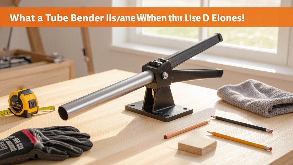
A tube bender is a tool composed of a bending die, a clamp or former, and a handle or hydraulic ram that together shape tubing without kinking.
It is commonly used across plumbing, HVAC, automotive, and metalworking to form bends for fluid lines, frames, and conduit.
Different styles—hand, press, rotary draw, and hydraulic—are selected based on tube material, diameter, and required bend radius.
Definition and basic components of a tube bender
Tube benders are hand or machine tools designed to bend metal tubing into precise angles and curves without collapsing or kinking the tube wall.
Basic components include a die or former, clamp or pressure die, bending arm, and degree gauge; some models add mandrels to support the ID.
Knowledge of how to use tube bender guarantees correct setup, alignment, and consistent, damage-free bends.
Common applications by industry (plumbing, HVAC, automotive, metalwork)
Following a clear understanding of a bender’s components and setup, the discussion moves to where the tool is most commonly used and why it matters for each trade.
Plumbers form precise water and gas runs; HVAC technicians shape refrigerant and duct tubing for leak-free routing; automotive professionals bend brake, fuel, and exhaust lines to fit tight chassis spaces; metalworkers create structural and decorative tubing with repeatable accuracy.
Types of tube benders and best use cases
Different types of tube benders serve distinct tasks, from simple hand-held spring benders for soft copper to hydraulic and CNC machines for thick-walled or high-volume work.
Selection depends on material, diameter, wall thickness, accuracy, and production volume.
- Spring benders: soft tubing, DIY
- Hand lever: precision, low volume
- Rotary draw: tight radii
- Hydraulic: thick walls
- CNC: high-volume, repeatable accuracy
Materials and Tubing Basics Relevant to Bending
Different tubing materials—copper, aluminum, mild steel, and stainless—have distinct ductility and springback that affect bend radius and tooling choice.
Wall thickness and outside diameter determine how easily a tube will form and whether support (like a mandrel) is needed to avoid collapse or wrinkling.
Accurate measurement and clear marks for centerline and start of bend are essential to achieve the desired geometry.
Tube materials and how they affect bending (copper, aluminum, steel, stainless)
Because each metal combines distinct strength, ductility, and work-hardening characteristics, the choice of tubing material—copper, aluminum, mild steel, or stainless steel—directly determines bend methods, springback, required tooling, and the likelihood of cracking or wrinkling. Copper bends easily with minimal springback; aluminum needs care for cracking; mild steel requires more force; stainless resists forming and work-hardens.
| Material | Behavior | Tooling |
|---|---|---|
| Copper | High ductility | Light dies |
| Aluminum | Moderate ductility | Rubber/mandrels |
| Steel/Stainless | Low ductility | Hardened dies |
Tube wall thickness, diameter, and bendability
Tube wall thickness and diameter are primary geometric factors that control how a tube responds to bending. Thicker walls resist ovalization and collapse, allowing tighter radii and reducing wrinkle risk.
Larger diameters increase bending force and tendency to flatten. Wall-to-diameter ratio and material ductility together determine allowable bend radius, springback amount, and whether internal support or heat is required.
Measuring and marking tubing accurately before bending
Having established how wall thickness, diameter, and material affect bendability, attention turns to measuring and marking—steps that translate theoretical limits into accurate bends.
Measure from fixed datum, allowing bend allowance and springback, and mark with fine, visible lines. Use calipers, protractors, and a center punch for repeatable reference points.
Verify layout against templates before clamping or bending to avoid costly errors.
Choosing the Right Tube Bender and Accessories
Choosing the appropriate tube bender requires weighing manual, hydraulic, and electric options for their precision, power, and cost.
Equally important is matching dies and bend radii to the tubing material and the anticipated bend to prevent kinking or deformation.
Finally, selecting essential accessories—such as backup dies, mandrels, and proper PPE—ensures accurate bends and operator safety.
Manual vs. hydraulic vs. electric benders: pros and cons
When selecting between manual, hydraulic, and electric benders, users should weigh capacity, control, speed, and cost to match tool performance with project demands. Manual offers low cost and tactile control; hydraulic provides high capacity with moderate setup; electric delivers speed and repeatability but higher expense. Choose based on material, volume, portability, and budget.
| Type | Strength | Typical Use |
|---|---|---|
| Manual | Low cost | Light jobs |
| Hydraulic | High force | Thick tubing |
| Electric | Fast | Production work |
Selecting the correct die/radius for desired bend
After matching a bender type to project needs, attention turns to selecting the correct die and bend radius, since those determine tube fit, wall behavior, and final geometry.
Choose a die matching tube outer diameter and profile; select radius based on material, wall thickness, and required bend tightness to prevent collapse or excessive thinning.
Verify tooling compatibility and bend allowance for accurate layout.
Essential accessories and safety gear
Although proper dies and radii set the stage for a successful bend, selecting the right accessories and safety gear is equally critical to protect the operator and preserve tube integrity.
Essential items include protective eyewear, gloves, clamps, mandrels, and formers to prevent collapse and injury.
- Safety glasses
- Cut-resistant gloves
- Tube support clamps
- Internal mandrels
- External formers
Preparing for a Clean, Accurate Bend
Before bending, the tubing should be inspected for dents, cracks, or contamination and cleaned inside and out to prevent defects.
Calculations for bend allowance, machine take-up, and expected springback must be completed so the final geometry is accurate.
Finally, the workpiece should be firmly secured and the bender set up with the correct dies and stops to guarantee repeatable, clean bends.
Inspecting tubing for defects and cleaning interior/exterior
Inspect the tube thoroughly for dents, cracks, corrosion, and uneven wall thickness, paying close attention to areas near fittings and ends where stress concentrates.
Remove burrs, scale, oils, and debris from exterior and interior using appropriate brushes, solvents, or compressed air.
Verify dimensional uniformity and roundness.
Mark defect-free bending zones and replace or repair contaminated, compromised, or nonconforming sections before bending begins.
Calculating bend allowances, take-up, and springback
Calculate precise bend allowances, take-up, and expected springback to guarantee the finished tube meets dimensional and fit-up requirements.
Use material-specific K-factors or bend allowance formulas to determine developed length.
Account for tooling-induced take-up (offset between clamp and die center).
Estimate springback from material yield and bend radius, and plan compensating overbend angles so final geometry conforms to drawings.
Securing the workpiece and setting up the bender
With bend allowances, take-up, and springback determined, attention turns to securing the tube and configuring the bender so the calculated geometry is achieved on the shop floor.
Clamp the tube firmly with soft jaws to prevent marring. Align reference marks with die centerline, set bend angle stops, adjust pressure die and wiper position, and verify backstop and rotation limits before a trial bend.
Step-by-Step Tube Bending Process
The step-by-step tube bending process begins with marking the start and tangent points on the tube and proceeds through setting the die and aligning the tube for an accurate bend.
Next, the operator performs the bend—using the appropriate technique for manual or powered benders—then releases the tube and checks the bend angle.
Finally, the tube is trimmed, deburred, and given a final measurement to confirm conformity.
Step 1 Marking start and tangent points
Begin by identifying the tube’s start point and the tangent point where the bend will shift from straight to curved.
The technician measures from reference edges, notes centerline positions, and marks both points with a scribe or tape.
Include bend radius information and rotation orientation.
Verify marks against the bending plan, double-check distances, and confirm marks are visible and unambiguous before proceeding.
Step 2 Setting the die and aligning the tube
Position the appropriate die on the bender and secure it according to the machine’s specifications, ensuring the die radius matches the marked bend and that clamping surfaces are clean and free of debris.
The operator aligns the tube with the die’s centerline, sets the clamp block at the start mark, checks feed length and rotation, and verifies squareness and clearance before applying pressure.
Step 3 Performing the bend (technique for manual and powered benders)
Applying steady, controlled force brings the tube into the die to form the bend; operators should follow a smooth, continuous motion on manual benders and a monitored, incremental feed on powered machines to prevent kinking or springback.
The operator maintains consistent pressure, watches for material deformation, and pauses briefly if resistance spikes.
Use backing or internal supports as specified for thin-walled or long sections.
Step 4 Releasing and checking the bend angle
Release the tooling slowly and retract any supports once the bend cycle completes to prevent sudden springback or distortion.
The operator then measures the bend angle with a protractor or digital gauge, comparing to the template or drawing. If angle deviates, minute corrective bends are applied cautiously.
Inspect the tube for ovality, wall thinning, surface marks, and confirm clamp and die alignment before proceeding.
Step 5 Trimming, deburring, and final measurement
With the bend verified and any minor corrections made, the operator prepares the tube for finishing by marking trim points per the drawing and securing the workpiece to prevent movement.
The tube is cut to length, burrs removed with a deburring tool or file, and internal edges cleaned.
Final measurements and fit checks confirm tolerances before any surface treatment or installation proceeds.
Advanced Techniques for Precise Results
The section outlines advanced methods for achieving precise tube bends, including techniques for executing compound bends and offsets.
It also covers strategies for working in confined spaces and using box-frame approaches to control geometry.
Finally, it explains how fillers, sand, and internal mandrels prevent collapse and preserve wall integrity.
Making compound bends and offsets
Mastering compound bends and offsets requires careful planning, precise measurement, and controlled bending sequences to guarantee alignment and avoid tube deformation.
The operator maps bend centers, calculates cumulative bend angles, and sequences bends to prevent springback and collision.
Use templates or CAD-derived jigs, verify dimensions after each bend, and trim or rework gradually rather than forcing corrections to maintain wall integrity and fit.
Bending in tight spaces and box-frame techniques
When space constraints or surrounding structures limit access, operators adapt tooling, sequencing, and support methods to maintain bend accuracy and tube integrity.
Techniques include using compact mandrels, low-profile die sets, and staged partial bends to clear obstructions.
Fixtures and temporary clamps stabilize tubes inside box frames while incremental forming prevents springback.
Careful measurement and mock-up verify fit before final installation.
Using fillers, sand, or internal mandrels to prevent collapse
Reinforce tubes internally to prevent collapse during bending by using fillers—such as tubular mandrels, sand, or expandable plugs—that support the wall and maintain cross-sectional shape.
Choose a mandrel sized to fit, or pack fine dry sand and seal ends to avoid shifting. Expandable plugs offer quick setup for thin walls.
Guarantee secure retention and lubricate to reduce friction and scoring during the bend.
Common Problems and How to Fix Them
Common tube-bending problems include kinking, wrinkling, and flattening, each with specific causes and straightforward remedies such as internal supports or adjusted bend radii.
Incorrect angles can often be corrected by measured re-bending or using adjustable stops to prevent repetition of the error.
Springback and overbend are managed by anticipating material behavior, applying controlled overbend, or using backup dies to achieve the desired final angle.
Kinking, wrinkling, or flattening: causes and remedies
Kinks, wrinkles, and flattened sections result from uneven material flow, insufficient internal support, or incorrect tooling geometry. Recognizing the specific defect quickly directs the appropriate remedy.
Use internal mandrels, correct die radius, adequate lubrication, slower bending speed, and proper clamping to restore form; replace damaged tube if beyond repair.
- Mandrel support
- Correct die radius
- Lubrication
- Slow, steady feed
- Proper clamp pressure
Incorrect angles and how to correct or re-bend
After addressing material flow and support to prevent kinks and wrinkles, attention turns to incorrect bend angles, which usually arise from measurement error, springback miscalculation, or slippage in the clamp.
Correction begins by marking actual versus planned angles, loosening clamps slightly to rebend small amounts, using fixtures or jigs for precision, and trimming or remaking sections when distortion or metal fatigue prevents accurate rework.
Dealing with springback and overbend strategies
Many bends require anticipating springback—metal’s elastic recovery that reduces the achieved angle once pressure is released—so operators often intentionally overbend by a calculated amount to reach the target.
Empirical testing, material charts and bend-radius formulas define the overbend. Smaller radii and harder alloys need more compensation.
Verify with test pieces, adjust die selection or clamp pressure, and document settings for repeatable accuracy.
Safety Considerations and Maintenance
The section outlines essential personal protective equipment and safe operating practices to minimize injury during bending operations.
It then covers routine maintenance tasks for both manual and hydraulic benders to guarantee reliable performance.
Finally, it addresses proper storage and care of dies and accessories to prolong tool life and maintain bending accuracy.
Personal protective equipment and safe operating practices
Wear appropriate personal protective equipment and follow strict operating procedures to minimize injury when using a tube bender.
Operators should remain attentive, secure workpieces, and avoid loose clothing. Emergency stop knowledge and clear work areas reduce risk.
- Safety glasses
- Cut-resistant gloves
- Steel-toe footwear
- Hearing protection
- Tight-fitting clothing and no jewelry
Routine maintenance for manual and hydraulic benders
Perform regular inspections and basic upkeep to guarantee manual and hydraulic tube benders operate safely and reliably.
Check for hydraulic leaks, fluid levels, and hose integrity; replace or top up as manufacturer specifies.
Lubricate pivots, bearings, and slide surfaces.
Tighten fasteners, inspect frames for cracks or deformation, and verify pressure gauges and safety valves function.
Document maintenance and schedule periodic professional servicing.
Storage and care of dies and accessories
Proper storage and care of dies and accessories preserves tooling accuracy and reduces downtime after routine maintenance of the bender.
Dies should be cleaned, dried, and lightly oiled, then stored in labeled, foam-lined racks to prevent nicks.
Inspect accessories for wear before use, replace damaged parts, and document storage locations and maintenance dates.
Controlled humidity and secure cabinets extend tool life.
Cost, Time, and Quality Trade-offs
Decision whether to bend tubing by hand or outsource hinges on volume, required precision, and available equipment.
Time and cost estimates should account for setup, per-bend labor, material waste, and any outsourcing fees.
Quality checkpoints for professional work include dimensional tolerances, surface finish, and absence of cracking or deformation.
When to bend by hand vs. when to outsource
When should a fabricator bend tubing by hand and when is it wiser to outsource the job? The decision balances volume, precision, equipment, and risk tolerance. Small runs, simple radii, or prototypes suit hand bending; high quantities, tight tolerances, or exotic alloys favor outsourcing to specialists with jigs and CNC.
| Choice | Feeling |
|---|---|
| Hand | Control |
| Outsource | Relief |
| Small run | Empowered |
| Large run | Confident |
| Prototype | Curious |
Estimating time per bend and cost factors
After weighing whether to bend by hand or send work out, the next practical consideration is how long each bend takes and what drives cost.
Time per bend depends on tube material, diameter, wall thickness, tooling setup and operator skill.
Batch size, machine type (manual versus CNC), scrap rate and secondary operations (deburring, fittings) determine labor and overhead, informing per-bend pricing.
Quality checkpoints for professional work
Balance quality, speed, and cost by applying a short list of objective checkpoints at key stages of the bending process.
Inspect material selection, tooling condition, and setup accuracy before bending.
Monitor bend radius, springback, and wall thinning during operation.
Verify dimensional tolerances, surface finish, and joint fit afterward.
Record cycle time, scrap rates, and rework to optimize cost versus quality.
Quick Reference Cheat Sheet
The quick reference cheat sheet lists standard bend radii and common material limits for rapid selection.
It provides a concise step checklist for making a single bend from setup through release.
It also offers brief troubleshooting tips for common issues like kinking, springback, and misalignment.
Standard bend radii and common material limits
A compact cheat sheet lists standard bend radii and common material limits to guide quick decisions when forming tube and pipe; it pairs typical radius-to-diameter ratios (R/D), minimum bend radii by material, and practical wall-thinning or wrinkle thresholds so users can match tools and processes to workpiece constraints without extensive calculation.
| Material | R/D | Limit |
|---|---|---|
| Steel | 1.5 | slight thinning |
| Aluminum | 2.0 | moderate wrinkle risk |
| Copper | 1.0 | springback concerns |
| Stainless | 2.5 | work hardening |
Step checklist for a single bend
Begin by confirming workpiece specifications and machine setup: verify tube material, outer diameter, wall thickness, desired bend angle and radius, tooling compatibility, and bend direction.
Then guarantee the bender is fitted with the correct die, clamp, and pressure die settings and that material support and backup mandrels (if required) are in place.
- Set bend origin and backstop
- Align tube and mark
- Apply proper clamp pressure
- Execute controlled bend cycle
- Measure and release gently
Troubleshooting quick tips
Refer to this concise cheat sheet when common tube-bending issues arise to quickly identify causes and corrective actions.
Common faults, prevention steps, and quick fixes are listed for fast reference.
- Kinked tube: increase bend radius, use internal support
- Springback: overbend slightly, verify material springback data
- Surface scuff: use protective pads
- Misalignment: reposition mandrel and clamp
Conclusion
A tube bender becomes a reliable compass guiding metal into precise curves, its operator learning when to trust tools and when to measure twice. With correct material choice, proper setup, and methodical technique, bends remain clean and accurate while common issues are anticipated and corrected. Regular safety checks and maintenance keep results consistent over time. Ultimately, informed trade-offs between cost, speed, and finish guarantee each bent tube fits its designed purpose.
