How to Measure Pipe Size: Quick Guide for DIY & Plumbing Pros
To measure pipe size accurately, start by determining the outside diameter (OD) using calipers or a tape measure. Note the wall thickness to calculate the inside diameter (ID) or schedule. Remember to use OD for fittings and ID for flow calculations, as nominal sizes may not match the measured values. Visually identify the pipe material (PVC, copper, steel, PEX) and confirm the thread type for any threaded joints. Record all measurements and markings for easy reference during replacements. This process will help you match parts correctly and ensure safe installations.
Key Takeaways:
- Measure OD for fittings, ID for flow calculations.
- Identify pipe material and thread type.
- Record measurements for future reference.
How to Measure Pipe Size : OD vs ID (Quick Answer)
Understanding pipe size begins with distinguishing outside diameter (OD) from inside diameter (ID): OD measures the pipe’s external width, while ID measures the internal passage through which fluid flows.
OD is straightforward to measure with calipers; ID requires measuring wall thickness and subtracting twice that from OD or direct measurement if accessible.
For fittings and clearances, OD determines external fit while ID governs flow capacity and pressure loss.
Material and manufacturing variances mean nominal sizes may not equal measured values.
Accurate measurement supports correct selection, proper sealing, and predictable hydraulic performance in installation and maintenance tasks.
Which Pipe Measurement to Use (Nominal, OD, ID, Schedule)
Choosing which pipe measurement to use depends on the task: nominal size for specification and compatibility, outside diameter (OD) for fittings and clearances, inside diameter (ID) for flow calculations, and schedule (or wall thickness) for pressure capacity and strength. A concise guide helps match measurement to purpose: use nominal sizes for buying and matching parts, OD when routing or selecting clamps, ID for hydraulic sizing, and schedule when pressure or strength matters. When unsure, check fittings and system requirements.
| Measurement | Use case | Quick tip |
|---|---|---|
| Nominal | Specification | Match part numbers |
| OD | Fittings/clearance | Measure with calipers |
| ID | Flow | Use for velocity calculations |
| Schedule | Pressure/strength | Higher schedule = thicker wall |
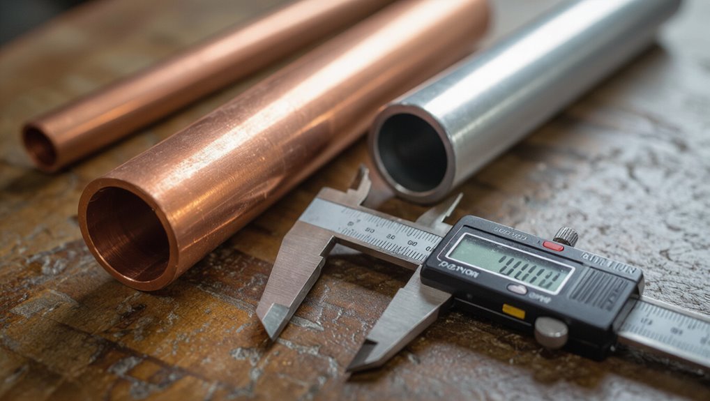
Identify Pipe Material Fast: PVC, Copper, Steel, PEX, CPVC
An observer can quickly distinguish PVC, copper, steel, PEX, and CPVC by visual cues like color, fittings, and surface texture.
Simple touch checks—temperature and rigidity—help confirm whether a pipe is metal, soft plastic, or flexible tubing.
Manufacturer markings, stamps, or printed labels on the pipe provide the most reliable identification when present.
Visual Appearance Cues
Visual cues let a person quickly distinguish common plumbing materials by color, finish, and fittings.
Observation of hue, sheen, and joint type identifies PVC (smooth white/gray, solvent-welded fittings), CPVC (cream/tan, similar joints), copper (reddish-brown, soldered or press fittings), steel (dark, threaded or welded, may be galvanized silver), and PEX (flexible, colored tubing with crimp rings).
- PVC: rigid, uniform color, printed size markings.
- CPVC: slightly yellowed or beige, similar markings.
- Copper: metallic luster, seams or brazing.
- PEX: flexible, often red/blue/white, plastic fittings.
Touch And Temperature
After noting color and fittings, touch and temperature provide quick tactile clues to pipe material.
Hands detect warmth: copper and steel feel cool to the touch, often colder than surrounding air, while plastic types (PVC, CPVC, PEX) feel closer to ambient temperature and warmer.
Surface texture distinguishes materials: copper is smooth and solid, steel may feel heavier and slightly rougher or welded at seams, PVC/CPVC are smooth and rigid, PEX feels slightly flexible and softer.
Flex testing with gentle pressure helps: PEX yields subtly, plastics resist bending more than metal.
Use gloves for safety and to avoid misleading skin temperature.
Markings And Labels
Markings and labels on pipe are fast, reliable identifiers because manufacturers emboss or print material type, size, pressure rating, and standards directly on the surface. This lets a user quickly distinguish PVC, CPVC, PEX, copper, and steel without cutting or testing.
Color bands and abbreviations (e.g., SCH40, CTS, K, SDR) clarify dimensions and application. When faded, cleaning or rotating the pipe reveals hidden text. Match codes to reference charts or manufacturer sites for confirmation.
Note that fittings may lack markings, so inspect adjacent pipe sections.
- Read printed material and size codes.
- Check pressure and temperature ratings.
- Use color bands as secondary clues.
- Verify against manufacturer specs.
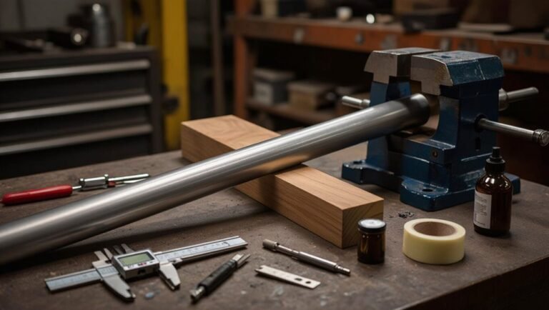
Measuring Outside Diameter (OD) : Tools and Tips
Measuring a pipe’s outside diameter (OD) requires simple tools and careful technique to get an accurate value used for fitment and material specification. The technician selects calipers or an OD tape, positions jaws or tape perpendicular to the axis, and measures at several points to account for ovality. Clean the pipe and avoid compressing soft materials. Record the largest consistent reading; match to pipe standards for nominal sizing. For larger pipes, use a laser distance gauge or flexible tape with a rigid straightedge for reliability.
| Tool | Best for | Accuracy |
|---|---|---|
| Vernier caliper | Small metal pipes | ±0.02 mm |
| OD tape | Curved surfaces | ±0.5 mm |
| Laser gauge | Large diameters | ±1 mm |
Measuring Inside Diameter (ID) : When and How
When internal clearance, flow calculations, or fittings require precise dimensions, determining a pipe’s inside diameter (ID) becomes essential; technicians choose methods based on size, access, and material.
For exposed ends, calipers measure across the bore directly; for long runs, telescoping gauges capture ID before micrometer reading.
For flexible or soft materials, use mandrels or ball gauges to avoid deformation.
For inaccessible runs, pressure-based flow meters or ultrasonic internal profiling estimate ID indirectly.
Choose non-destructive methods for installed systems.
- Calipers for direct bores
- Telescoping gauges plus micrometer
- Mandrels/ball gauges for soft pipes
- Ultrasonic or flow-based estimation
Convert OD to Nominal Size Using Pipe Schedule
Many pipe systems require translating an outside diameter (OD) measurement into the corresponding nominal pipe size, and the pipe schedule provides the necessary wall-thickness context to do so.
The schedule designation (e.g., SCH 40, SCH 80) defines wall thickness for a given nominal size; combined with OD it yields the ID. To convert, measure OD accurately, consult a standard chart matching OD and schedule to nominal size, or calculate ID = OD − 2×wall thickness.
This method resolves ambiguities where different nominal sizes share similar ODs under varying schedules. Record schedule when identifying or ordering replacement pipe.
Read Stamped Markings and Color Codes to Confirm Size
Stamped size markings on pipe ends provide a direct, often manufacturer-applied indication of nominal diameter and schedule.
Color bands or painted stripes serve as quick visual codes for pipe type and planned service, which can corroborate stamped information.
Together, these markings help confirm measured dimensions and reduce reliance on caliper readings alone.
Stamped Size Markings
Pipe manufacturers often imprint size information directly onto the outside of the pipe using stamped markings and color bands; these provide a quick, verifiable reference to nominal diameter, wall thickness (schedule), and material grade.
Stamped markings are typically raised or engraved letters/numbers indicating NPS/OD, schedule or wall thickness, material specification (e.g., ASTM), and heat or batch codes. Inspectors should clean the surface to read faint stamps and compare markings to measurement tools when in doubt.
Stamps offer permanence absent paint wear.
- Location: along the pipe length, repeat marks.
- Format: standardized abbreviations.
- Durability: metal stamping resists weather.
- Verification: cross-check with calipers.
Color Band Identification
A system of painted color bands provides a fast visual cue to nominal diameter, wall thickness, and material grade, allowing inspectors to confirm stamped markings at a glance. Color codes vary by standard; users should reference the project’s legend. Inspectors note band sequence, width, and position relative to fittings. Faded or overlapping paint requires cleaning before reading. Where codes conflict with stamps, priority follows contract or governing spec. Photographs with a scale help remote verification. Routine checks reduce installation errors and guarantee replacement parts match system requirements.
| Band Position | Meaning | Typical Color |
|---|---|---|
| Outer | Material grade | Green |
| Middle | Nominal size | Yellow |
| Inner | Wall thickness | Red |
Measure Buried or Hidden Pipes Without Cutting Them
Detecting the diameter of a buried or hidden pipe without cutting into it requires indirect measurements and the right tools, such as inspection cameras, ultrasonic thickness gauges, or tracer wires paired with a receiver.
Professionals map pipe runs, note access points, and combine external measurements with material knowledge to infer internal diameter.
Inspection cameras reveal internal profile; ultrasonic gauges estimate wall thickness to deduce bore when material and OD are known; tracer systems locate runs and depth.
Accurate records and multiple methods reduce guesswork.
- Camera inspection for internal view
- Ultrasonic for wall/OD data
- Tracer for location/depth
- Combine records and measurements
Measuring Fittings: Threads, Unions, and Flanges
Measuring fittings requires attention to thread type and pitch as well as the nominal size marked on the fitting.
For threaded fittings, a thread gauge and calipers determine threads per inch (or pitch) and outer diameter to identify the standard.
For unions and flanges, measure the mating face dimensions, bolt circle diameter, and gasket face to confirm compatibility.
Measuring Threaded Fittings
How should one approach measuring threaded fittings to guarantee compatibility and leak-free connections? A precise method prevents mismatches.
Identify thread type (NPT, BSPT, BSPP) visually and with gauges. Measure major diameter with calipers, count threads per inch (TPI) or pitch using a gauge, and note taper presence.
Record material and pressure rating for compatible mating parts. Use thread identification charts to confirm standards before installation.
Apply appropriate sealant or tape for tapered threads only. Verify fit by careful hand-starting; avoid cross-threading.
Accurate measurements guarantee reliable assemblies and reduce leaks or repair needs.
- Identify thread standard
- Measure major diameter
- Count TPI or pitch
- Note taper and material
Checking Flange Dimensions
When preparing to mate flanged fittings, verify each flange’s critical dimensions—bolt circle diameter (BCD), number and size of bolt holes, flange outer diameter (OD), hub/raised face dimensions, and flange thickness—to affirm proper alignment and gasket seating.
Measure BCD with calipers or a scale between hole centers; confirm bolt hole diameter and spacing match fasteners. Record flange OD to affirm clearance and piping support fit.
Check raised face height and diameter for correct gasket type and compression. Verify thickness and hub profile for pressure rating compatibility.
Document standards (ANSI, DIN, JIS) stamped on the flange to affirm interchangeability.
Sizing Threaded Pipe: NPT vs BSP and Measurement Effects
Threaded pipe sizing requires careful attention to thread standard and measurement location because National Pipe Taper (NPT) and British Standard Pipe (BSP) threads differ in form, pitch, and nominal sizing conventions.
The article explains that NPT is tapered, BSP comes in parallel (BSPP) or tapered (BSPT), and nominal size does not equal actual OD.
Measurement should record thread type, major/minor diameters, threads per inch (TPI) or pitch, and whether fitting seals on threads or a seat.
Adapters, runout, and manufacturing tolerances affect fit and flow.
- Identify thread standard
- Measure major OD
- Count TPI or pitch
- Note taper or parallel
Convert Metric and Imperial Pipe Sizes (Simple Tables)
Having established how thread standards and measurement locations affect nominal and actual pipe dimensions, converting between metric and imperial pipe sizes requires a straightforward reference that maps common nominal sizes to their equivalent outside diameters, wall thicknesses, and thread pitches. A concise table helps match fittings and specify materials: choose the nearest OD, confirm wall (schedule or PN), and verify thread form. For quick conversion, refer to common pairs below; these cover typical trade sizes and offer a starting point before detailed spec checks.
| Nominal (Imperial) | OD (mm) | Wall / Thread |
|---|---|---|
| 1/2″ | 21.3 | 2.77 mm / 14 tpi |
| 3/4″ | 26.7 | 2.87 mm / 14 tpi |
| 1″ | 33.4 | 3.38 mm / 11.5 tpi |
Common Measurement Mistakes DIYers Make : Avoid These
Although measurements seem straightforward, DIYers frequently misidentify whether they are recording nominal size, actual outside diameter, or thread pitch, which leads to mismatched fittings and leaks.
Common errors include confusing pipe schedule with diameter, measuring only visible length, and ignoring thread form or taper. Misreading markings or using household rulers without checking calibration also causes wrong purchases.
Attention to what each measurement represents prevents wasted time and materials.
- Confusing nominal vs. actual OD
- Measuring interior instead of exterior walls
- Overlooking thread pitch/type (NPT vs BSP)
- Using uncalibrated tools or visual estimates
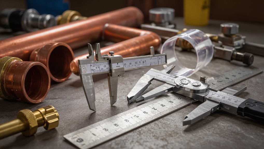
Essential Measuring Tools for Pipe Sizing
The next section outlines the essential tools used to measure pipe dimensions accurately.
It covers tape measure basics for quick overall length and diameter checks, calipers for precise external measurements, and pipe ID tools for identifying internal diameters and schedule.
Each tool’s purpose and best-use scenarios are briefly explained to guide proper selection.
Tape Measure Basics
A reliable tape measure is the foundational tool for accurate pipe sizing, providing quick external measurements of length, diameter, and run without specialized equipment. It allows clear recording of pipe lengths, offsets, and distances between fittings.
Users should confirm the blade’s markings are legible and the case is durable for jobsite use. When measuring curved or insulated pipes, note outer dimensions and account for insulation thickness separately.
Magnetic or hook-end tapes can stabilize measurements on metal pipes. Consistent technique reduces error: align zero point, avoid sag, and read at eye level.
- Verify blade graduations and condition
- Use hook to anchor ends
- Account for insulation
- Read at eye level
Caliper For Accuracy
Calipers offer precise internal and external diameter measurements that tape measures cannot match, making them indispensable for accurately sizing pipes, fittings, and bore dimensions. A caliper’s jaws and depth probe quickly capture outside, inside, and step measurements; digital models display readings in inches or millimeters, reducing conversion errors. Proper technique includes zeroing before use, measuring at multiple points to detect ovality, and applying gentle, consistent pressure. Maintenance—cleaning, battery checks, and calibration—preserves accuracy. Selection depends on required resolution and access to fittings.
| Type | Range | Typical Use |
|---|---|---|
| Vernier | 0–6″ | General shop |
| Digital | 0–12″ | Field accuracy |
| Dial | 0–6″ | Mechanical environments |
Pipe ID Tools
Accurate pipe identification requires more than precise diameter readings; it also calls for tools that determine wall thickness, material, thread type, and nominal size.
Pipe ID tools help confirm schedule and fit: calipers measure OD/ID; ultrasonic gauges determine wall thickness; thread gauges identify pitch and form; and material analyzers (XRF or simple magnet tests) distinguish metals and plastics.
Combined, they prevent mismatches and leaks. Proper use reduces installation errors and guarantees compatibility with fittings and pressure ratings.
Routine verification is recommended for repairs and retrofits to maintain system integrity and safety.
- Calipers for OD/ID
- Ultrasonic wall gauges
- Thread pitch gauges
- Material testers
When to Call a Pro: Gas, Code-Critical, and Complex Systems
When a job involves gas lines, code compliance, or multilayered systems, homeowners should defer to licensed professionals rather than attempt DIY measurements or repairs.
Certified plumbers and gas-fitters possess training, tools, and permitting knowledge required for safe sizing, leak testing, and proper venting. Code-critical work demands documented measurements, approved materials, and inspections; mistakes risk hazards, fines, or insurance denial.
Complex systems—boiler loops, commercial manifolds, combined HVAC/plumbing—require hydraulic calculations and coordinated trades.
Call a pro when unfamiliar fittings, concealed piping, or appliance connections are present, when permits are required, or when a reliable, code-compliant outcome is essential.
Quick Cheats to Match Old Pipes to Replacement Parts
If the original fittings are still accessible, a quick visual-check and a few simple measurements usually reveal the right replacement.
Inspect thread type, measure outside diameter, note wall thickness, and identify material (copper, galvanized, PVC). Match thread pitch with a gauge or compare to a known fitting.
For sweat joints, measure OD and prepare proper adapters. Photograph parts and stamp markings for supplier help.
- Confirm thread form (NPT vs BSP).
- Measure OD with calipers.
- Compare wall thickness for pressure ratings.
- Use photos and markings when ordering replacements.
Document Pipe Measurements for Maintenance and Permits
Documenting pipe measurements for maintenance and permits requires a clear, consistent record that captures size, material, thread type, wall thickness, joint method, and any identifying markings.
Records should list nominal diameter, measured OD/ID, schedule or actual wall thickness, and thread standard (NPT, BSP, metric). Note material (PVC, copper, steel, etc.), protective coatings, and age or manufacturer stamps.
Include photos with scale, date, location within the system, and orientation. Record measurement tools used and measurement uncertainty.
Store documentation in an accessible format for future work and permit submission; update entries after repairs or modifications.
Troubleshoot Nonstandard, Corroded, or Obsolete Pipes
Because nonstandard, corroded, or obsolete pipes often deviate from modern dimensions and materials, accurate diagnosis begins with careful inspection and measurement to identify hazards and viable repair options.
Technicians document visible corrosion, flange and thread types, wall loss, and atypical fittings. Use calipers for outer diameter, bore gauges for internal diameter, and thickness gauges for remaining wall. Photograph markings and joints for records.
When uncertain, send samples for metallurgical or pipe identification testing. Prioritize safety: isolate affected sections, test for lead or asbestos, and consult local codes before replacement or adaptation.
- Measure OD, ID, and wall thickness
- Identify material and markings
- Test for hazardous substances
- Match or specify replacements
Conclusion
In short, measuring pipe size correctly saves time, money, and headaches. The guide stresses when to use OD, ID, nominal, or schedule measurements, how to identify common materials, and which tools and tricks work best. For risky or code-critical jobs, a professional should be called. Keep clear records for maintenance and permits, and when matching or repairing old pipes, expect to roll up one’s sleeves and get pragmatic—measure twice, cut once.