How to Size a Gas Line: Step-by-Step Guide for Homes, Appliances & Safety
To properly size a gas line for your home, follow these steps to ensure appliances receive the right pressure and flow while maintaining safety. Begin by listing the BTU inputs of your appliances and converting them to CFH. Next, total the demand using diversity factors, measure the run lengths and equivalent fittings, and consult pipe-sizing charts or software to determine the appropriate diameters and materials (such as black iron, CSST, or copper). Ensure your installation complies with local codes, includes pressure testing, and is well-documented. Continue reading for detailed calculations, examples, and essential safety protocols.
How to Size a Gas Line for Homes and Appliances: Quick Overview
Proper gas line sizing guarantees appliances receive adequate pressure and flow while minimizing leak risks and maintaining code compliance.
Homeowners and technicians should reassess sizing when adding high-demand appliances, experiencing pressure drops, or when lines show age-related deterioration.
Replacement is recommended if inspections reveal corrosion, leaks, inadequate capacity, or noncompliant materials.
What proper gas line sizing achieves for safety and performance
Sizing a gas line correctly confirms appliances receive the right pressure and flow, reducing the risk of malfunction, incomplete combustion, or dangerous leaks.
Proper sizing enhances safety, optimizes efficiency, and prolongs appliance life by preventing pressure drops and soot buildup.
Clear guidance on how to size a gas line assures code compliance, reliable operation, and predictable performance under varied demand without excessive cost or risk.
When to re-evaluate or replace an existing gas line
After confirming that a gas line meets pressure and flow needs, homeowners and technicians should know when to re-evaluate or replace an existing run.
Re-evaluation is necessary after appliance upgrades, added fixtures, visible corrosion, leaks, pressure loss, or code changes.
Replacement is warranted for irreparable corrosion, outdated materials, inadequate capacity for new loads, repeated failures, or damaged piping following renovation or disaster.
Key Terms and Basics of Residential Gas Lines
The discussion begins by distinguishing residential fuels—natural gas and propane—and noting how their energy content and delivery affect sizing.
It then defines common materials and fittings such as CSST, black iron, and copper while reminding that PVC is not permitted for gas.
Finally, it outlines key units (BTU, CFH, PSI), explains pressure drop, and summarizes typical service pressures and the role of regulators.
Types of gas used in homes (natural gas vs propane)
Although both supply fuel for common household appliances, natural gas and propane differ in composition, pressure requirements, energy content, and delivery methods.
Natural gas (methane) is delivered via utility pipelines at lower pressure and yields less energy per unit volume.
Propane (liquefied petroleum gas) is stored on-site, requires higher delivery pressure, and provides greater energy density, affecting appliance settings and line sizing.
Common pipe materials and fittings (CSST, black iron, copper, PVC not allowed)
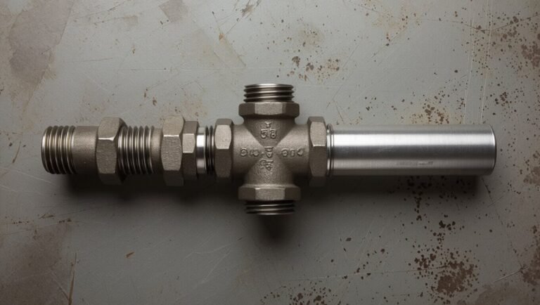
Common materials for residential gas lines include corrugated stainless steel tubing (CSST), black iron (steel) pipe, and copper, each chosen for specific installation contexts and code considerations.
CSST offers flexibility and fewer joints. Black iron is durable for mains and exposed runs, and copper suits some concealed applications where permitted.
Appropriate fittings, unions, threaded connections, and bonding/grounding practices guarantee safe, code-compliant installations.
Units of measure: BTU, cubic feet per hour (CFH), PSI, and pressure drop
Understanding gas-line measurements is essential for matching appliance demand to supply capacity and ensuring safe, code-compliant installations.
BTU quantifies heat output; appliances list BTU/hr. CFH measures gas volume flow required at a given heating value.
PSI denotes pressure; working differences determine flow. Pressure drop describes loss over length and fittings, used with charts to size pipe so appliances receive adequate CFH.
Standard service pressures and regulator roles
Because gas appliances and distribution systems operate at different pressures, residential service includes prescribed inlet pressures and pressure-reduction steps to guarantee safe, consistent delivery.
Typical utility supply is 7–14 inches water column (≈0.25–0.5 psi) to meter. Regulators step down and stabilize pressure for appliances (commonly 3–11 inches WC for natural gas, 10–11 inches WC for propane), preventing overpressure and ensuring proper combustion.
Calculating Gas Demand for Your Home
The homeowner should begin by listing every gas appliance, model, and input rating to create a complete inventory.
Each appliance’s BTU or CFH rating is then noted or converted as needed, and BTU ratings are translated to CFH using the appropriate energy content for natural gas or propane.
Finally, total demand is estimated by summing individual demands and applying accepted diversity or simultaneity factors to determine the peak load for sizing.
How to create an appliance inventory
Start by listing every gas appliance in the home, noting each unit’s make, model, and input rating (BTU/hr or kW) as shown on the data plate or in the manual.
Record location, quantity, and typical simultaneous use. Keep manuals or photos for verification.
- Water heater: location, model, input
- Furnace/boiler: location, model, input
- Range/oven: location, model, input
- Dryer/generator: location, model, input
Determining individual appliance BTU/CFH ratings
With an appliance inventory complete, the next step is to convert each unit’s input rating into a common gas demand measure—either BTU per hour (BTU/hr) or cubic feet per hour (CFH)—so total load can be calculated.
Consult nameplate or manual for input BTU/hr; if only kW or MJ is given, convert to BTU.
For CFH, divide BTU/hr by gas heating value (BTU/ft³) used locally.
Estimating total simultaneous demand vs diversity factors
Although every appliance’s input can be summed to produce a theoretical maximum load, it rarely reflects actual simultaneous usage; estimating total gas demand requires applying diversity (or simultaneity) factors to account for the probability that not all appliances run at full input at the same time.
Apply standard diversity tables or local code percentages, adjust for occupancy patterns, peak cooking/heating overlaps, then sum adjusted demands for sizing.
Converting BTU to CFH for natural gas and propane
Converting appliance input ratings from BTU/hr to cubic feet per hour (CFH) translates heat demand into the volumetric gas flow needed for sizing; this requires dividing the BTU/hr value by the fuel’s heating content—typically about 1,030 BTU per cubic foot for natural gas and about 2,516 BTU per cubic foot for propane—and then accounting for meter and regulator tolerances or local correction factors.
Apply rounding, sum appliance CFH, and compare with pipe capacity tables.
Step-by-Step Gas Line Sizing Procedure
The procedure begins by measuring the required run length and clearly identifying the routing.
Next, one consults published pipe sizing charts, calculates allowable pressure drop for the system, and selects pipe material and diameter to meet the load and length.
Finally, fittings, valves, and potential future additions are accounted for to guarantee the chosen layout maintains adequate pressure and capacity.
Step 1 Measure required run length and identify routing
Step 1 requires measuring the total run length of the gas line and identifying its routing from the meter or regulator to each appliance, including any branches, offsets, and entrance/exit points.
The technician records straight-line and actual lengths, notes vertical rises, elbow and fitting locations, and any concealed sections.
Accurate routing documentation guarantees correct pressure drop calculations and avoids overlooked restrictions or future access issues.
Step 2 Reference published pipe sizing charts and tables
After confirming run lengths and appliance loads, the technician consults published gas pipe sizing charts and manufacturer tables to select the correct pipe diameter for both natural and LP gas. Charts list flow capacity, pipe length, and allowable pressure. The technician matches appliance BTU to chart entries, selects the smallest acceptable diameter, and records the reference for installation and inspection.
| Flow (BTU/hr) | Length (ft) | Diameter (in) |
|---|---|---|
| 20,000 | 10 | 1/2 |
| 50,000 | 30 | 3/4 |
| 100,000 | 100 | 1 |
| 200,000 | 200 | 1 1/4 |
Step 3 Calculate pressure drop and allowable loss for your system
Next, calculate the actual pressure drop along the run and compare it to the system’s allowable loss to guarantee adequate delivery.
Determine gas flow rate, pipe length, fittings count and equivalent length, and inlet and outlet pressures.
Use appropriate formulas or software to compute pressure loss per unit length, sum losses, then verify total drop stays within the allowable limit for safe, efficient appliance operation.
Step 4 Select pipe material and diameter based on load and length
With the calculated allowable pressure loss confirmed, attention shifts to choosing the pipe material and diameter that will carry the required load over the measured length.
The installer evaluates materials (black steel, CSST, copper, polyethylene) for pressure rating, corrosion resistance, and code acceptance.
Using flow tables or software, they select a nominal pipe size that maintains pressure within limits across the run.
Step 5 Account for fittings, valves, and future additions
Several factors beyond straight-run length — fittings, valves, meters, and potential future additions — must be included in the sizing calculation because each contributes measurable pressure loss or added demand.
Calculate equivalent length for elbows, tees, and valves, add meter and regulator losses, and include foreseeable appliance additions.
Convert total equivalent length to sizing tables or formulas, adjusting pipe diameter to maintain required pressure and flow.
Step 6 Final verification with manufacturer specs and local code
After totaling equivalent lengths and selecting a provisional pipe size, the final verification stage requires cross-checking those choices against manufacturer specifications and local code requirements.
The installer confirms allowable pressure drop, appliance inlet pressures, and connector types specified by manufacturers, then guarantees compliance with jurisdictional tables, burial depths, venting rules, and permitting.
Any discrepancy triggers resizing, pressure testing, or authority consultation before installation.
Sizing Examples and Worked Calculations
The following worked examples illustrate typical gas‑line sizing scenarios: a short run to a single furnace, a branch supplying a kitchen and water heater, and a whole‑house service from meter to manifold.
Each example shows required BTU loads, pipe sizing steps, pressure drop checks, and final validation.
A brief troubleshooting section addresses common causes when calculated capacity does not match observed performance.
Example A Single appliance (furnace) short run
Precision guides this example, which walks through sizing a gas line for a single furnace on a short run by applying standard demand, pipe length, and pressure-drop criteria; it demonstrates how to determine required pipe diameter from the appliance’s input rating and the run length using the applicable sizing table or equation, highlights assumptions (service pressure, fittings, and piping material), and presents the calculation steps so a practitioner can reproduce the result.
| Step | Data |
|---|---|
| 1 | Input BTU |
| 2 | Run length |
| 3 | Pressure drop |
| 4 | Pipe material |
| 5 | Required diameter |
Example B Multiple appliances on one branch (kitchen + water heater)
When sizing a single branch that serves both a kitchen range and a water heater, the calculation must combine the individual appliance demands into a cumulative load, account for run length and fittings, and then select a pipe size that meets allowable pressure drop at the system service pressure.
This example walks through those steps with clear assumptions (appliance BTU ratings, effective length, number of elbows, piping material, and service pressure) so the required diameter can be reproduced and verified.
Assume 40,000 BTU range and 50,000 BTU water heater, 60 ft effective length, three elbows, black iron piping, 7″ w.c. service; cumulative 90,000 BTU requires 1″ pipe per tables for that length and pressure drop, verifying allowable velocity and pressure loss.
Example C Whole-house service from meter to manifold
Moving from a single branch calculation to a whole-house service requires combining individual appliance demands, diversity factors, and branch loads into a single cumulative demand at the meter.
Then, this capacity is allocated to a downstream manifold. This example presents a step‑by‑step sizing from meter to manifold using assumed fixture counts and appliance ratings, run lengths, fitting counts, piping material, and a specified service pressure.
Troubleshooting mismatches between calculated and observed performance
Diagnose discrepancies between calculated and observed gas system performance by systematically comparing assumed inputs, installation conditions, and measurement methods to field data.
Verify pipe lengths, fittings, elevation, and temperature; confirm meter and regulator settings; inspect for leaks, partial obstructions, or incorrect pipe materials.
Recalculate using measured pressures and flows, adjust friction factors, and document corrective actions or design revisions for future verification.
Code Requirements, Permits, and Professional Involvement
Local building codes dictate specific sizing limits, venting, shutoff placement, and mandatory inspection points for gas line work.
Licensed plumbers or certified gas technicians are required for permit-controlled installations and any changes to meter, service, or buried piping.
Copies of permits, inspection approvals, and safety certifications should be retained with the property records.
Typical local code requirements and inspection points
Many jurisdictions require permits, adherence to specific code sections, and formal inspections for new or altered gas lines to guarantee safety and compliance.
Inspectors typically verify correct pipe sizing, material types, joint methods, support and clearances, leak testing, venting and appliance connections, shutoff placement, and labeling.
Documentation of calculations, permits, and test results is often required before final approval.
When a licensed plumber/technician is required
After inspectors confirm sizing, materials, and testing, the question often turns to who must perform the work.
Jurisdictions typically require a licensed plumber or gas technician for installations, alterations, or mains tie-ins. Professionals hold required certifications, carry insurance, and obtain permits.
Homeowners may handle minor appliance connections where allowed, but complex or code-sensitive work mandates licensed involvement to guarantee compliance and safety.
Safety certifications and documentation to keep
When gas work is performed, the responsible parties must retain specific certifications, permits, and inspection records to demonstrate compliance with code and to support future maintenance or transfers of ownership.
Required documents typically include contractor licenses, permit approvals, test pressure results, inspection certificates, appliance-specific compliance tags, and any manufacturer installation instructions.
Store originals and digital copies; provide them to inspectors, buyers, and service technicians as needed.
Safety Considerations and Testing Procedures
The discussion shifts to essential safety checks and testing procedures required after sizing and installing a gas line.
It summarizes common leak-testing methods (soap solution and regulated pressure tests), outlines safe purging, ventilation, and ignition-control steps, and notes observable signs of under-sizing or unsafe installation such as persistent pressure drop, yellow flames, or pilot outages.
Emphasis is placed on following manufacturer instructions and local codes and on using qualified personnel for any live-gas work.
Leak testing methods (soap test, pressure test)
Begin leak testing with a clear plan and the correct equipment to confirm system integrity and guarantee occupant safety.
Use a soap solution to inspect fittings for bubbles at low pressure; mark and retest any suspect joints.
For whole-system verification, apply a calibrated pressure gauge and maintain test pressure for the required duration, monitoring for drops.
Document results and remedy any detected leaks before commissioning.
Procedures for purging, ventilation, and ignition safety
Perform purging, ventilation, and ignition-control procedures methodically to remove flammable mixtures, prevent accumulation of gas in confined spaces, and eliminate potential ignition sources before introducing gas into the system.
Technicians isolate sections, purge with inert gas or controlled air flow, verify clearance with calibrated detectors, guarantee continuous ventilation, disable electrical or open-flame sources, and follow manufacturer and code-required sequence checks before restoring service.
Recognizing signs of under-sizing or unsafe installation
After completing purging, ventilation, and ignition-control steps, attention shifts to detecting signs that a gas line is undersized or improperly installed.
Indicators include persistent low appliance flame or yellow tipping, pressure drop during simultaneous appliance use, unusual hissing or odors, loose fittings, corrosion, or uneven heating.
Immediate investigation, pressure testing, and qualified technician correction prevent leaks, carbon monoxide risk, and fire hazards.
Materials, Tools, and Installation Best Practices
The section outlines essential tools and measurement instruments for accurate pipe sizing and leak testing.
It covers accepted joining methods, proper supports, and corrosion protection to guarantee long-term integrity.
It also addresses routing, required clearances, and combustion-air provisions to maintain safe operation.
Recommended tools and measurement instruments
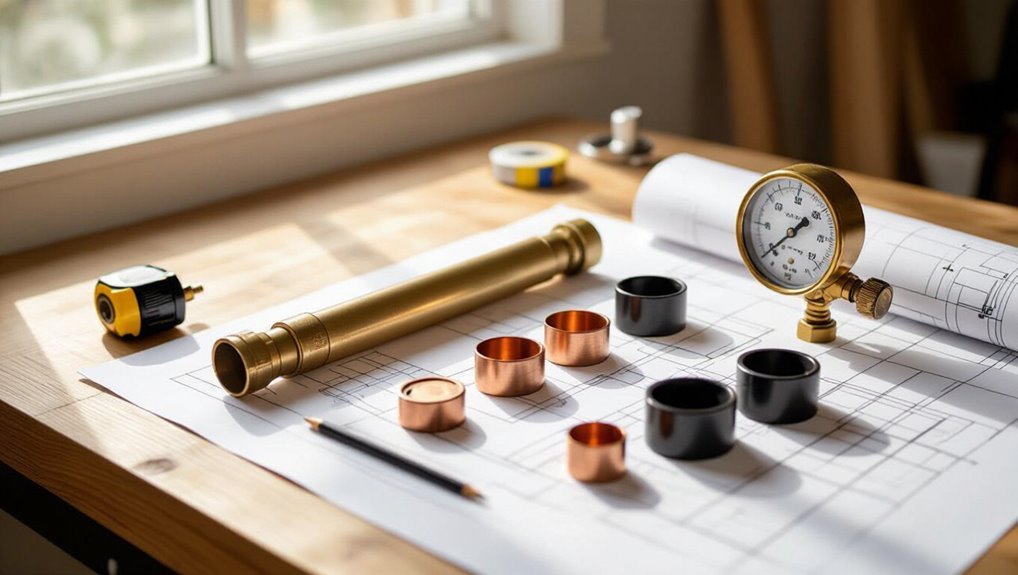
Accurate gas-line sizing relies on a specific set of tools and measurement instruments that guarantee safe, code-compliant installations.
Technicians use calibrated devices to measure pressure, flow, and pipe dimensions, ensuring correct capacity and minimal pressure drop.
Recommended instruments include:
- Manometer for static and working pressure
- Flow meter for BTU/CFH verification
- Pipe calipers/tape for diameter and wall thickness
- Gas leak detector for integrity testing
Joining methods, support, and protection from corrosion
Installers choose joining methods, supports, and corrosion protection based on pipe material, pressure class, and environment to guarantee long-term integrity and code compliance.
Compression, flared, welded, and approved mechanical couplings suit different materials.
Supports follow spacing per code, minimize stress, and prevent sag.
Corrosion protection uses coatings, cathodic protection, dielectric unions, and approved sealants.
Regular inspection preserves performance and safety.
Routing, clearances, and combustion air considerations
When planning gas-line routing, clearances, and combustion air needs, designers must account for pipe material, appliance type, building layout, and applicable codes to guarantee safe operation and serviceability.
Routes minimize bends, avoid ignition sources, and remain accessible for inspection.
Maintain manufacturer and code clearances around appliances, provide required combustion and ventilation air, seal penetrations appropriately, and document locations for future service and safety checks.
Common Mistakes and How to Avoid Them
Common errors in gas line sizing often stem from underestimating simultaneous demand, overlooking pressure drop on long runs, selecting improper materials or fittings, and failing to plan for future appliance upgrades.
Each mistake can lead to safety risks, poor performance, or costly retrofits. The following section identifies these pitfalls and gives practical steps to prevent them.
Undersizing due to neglecting simultaneous demand
Neglecting simultaneous demand leads to undersized gas lines when multiple appliances run at once but calculations assume they will not. This mistake underestimates peak load, causing low pressure, poor appliance performance, and potential safety issues.
Planners should aggregate realistic concurrent demand, apply diversity factors carefully, and verify total BTU requirements. Cross-check with codes and consult a licensed designer to prevent recurring undersizing errors.
Ignoring pressure drop over long runs
Long runs of gas piping can produce significant pressure drop, a factor often overlooked that reduces flow capacity and causes appliances to underperform or shut down.
Designers must calculate pressure loss per foot, account for fittings and elevation, and size mains accordingly.
Neglecting these calculations forces oversized appliances or inadequate performance; mitigation includes larger diameter pipe, parallel runs, or pressure-boosting solutions approved by code.
Wrong material or fitting choices
Choose appropriate materials and fittings with the same rigor used for sizing, because incompatible metals, incorrect thread types, or non‑rated components can cause leaks, corrosion, and safety failures.
Install gas‑rated pipes, fittings, and sealants; match threads (NPT vs BSP) and metallurgy; avoid cheap adapters.
Verify listings, pressure ratings, and local code approvals.
Improper choices increase leak risk and shorten service life.
Failing to account for future upgrades
What if the gas system is sized only for current appliances? Future additions—range, water heater, fireplace—can overload a marginally sized line, causing pressure drops and unsafe conditions.
Designers should project likely upgrades, add capacity margin, and choose accessible routings. Consulting code and a professional guarantees scalable sizing, avoiding costly rework, regulatory issues, and performance problems later.
Cost Considerations and Estimating Project Scope
Cost decisions hinge on material choices, labor rates, permit fees, and site-specific factors that affect total expense.
The article contrasts DIY approaches with professional installation risks and liabilities, emphasizing safety and code compliance trade-offs.
It also outlines how to obtain accurate quotes and key questions to ask contractors to define scope and avoid surprise costs.
Typical cost drivers (material, labor, permits)
Estimating a gas line project hinges on three primary cost drivers: materials, labor, and permits.
Materials vary by pipe type, fittings, regulators, and trenching supplies.
Labor reflects complexity, excavation, and licensed technician rates.
Permit fees depend on jurisdiction, required inspections, and possible impact fees.
Unexpected site conditions and code upgrades can increase totals, so contingency budgeting is advised.
Comparing DIY vs professional installation risks and liabilities
How much risk is acceptable when choosing between a DIY gas-line project and hiring a licensed professional depends on the homeowner’s skill, local regulations, and the specific scope of work.
DIY can lower upfront costs but increases liability, permit issues, code noncompliance risks, and safety hazards.
Professionals carry insurance, guarantee work, and simplify inspections, typically reducing long-term financial and legal exposure despite higher initial fees.
How to get accurate quotes and what questions to ask contractors
After weighing risks between DIY and professional installations, homeowners should focus on obtaining accurate contractor quotes to compare true costs and responsibilities.
Request itemized bids detailing materials, labor, permits, testing, and contingency. Ask about licensing, insurance, timeline, warranty, code compliance, and change-order policies.
Verify references, recent similar jobs, and written estimates. Compare at least three bids before deciding.
Resources, Charts, and Reference Tools
The article points readers to reliable pipe-sizing charts and online calculator tools for quick capacity and pressure-drop estimates.
It also recommends consulting manufacturer specification sheets and applicable code references to confirm equipment limits and installation requirements.
Finally, it notes where to find local code information and inspection contacts to guarantee compliance and obtain necessary approvals.
Reliable pipe-sizing charts and calculator tools
When sizing gas lines accurately, reliable charts and calculator tools serve as essential references that translate appliance BTU loads, pipe length, and pressure drop into recommended pipe diameters. They save time, reduce errors, and support informed decisions. Trusted tools offer clear inputs, units, and assumptions.
- Interactive online calculators
- Printable sizing charts
- Mobile apps with unit conversion
- Spreadsheet templates with formulas
Manufacturer specification sheets and code references
Manufacturer specification sheets and applicable code references provide the authoritative details needed to confirm pipe materials, maximum allowable pressures, required clearances, and approved installation practices. They list sizing tables, fittings, and derating factors; codes mandate inspection points and labeling. Cross-reference manufacturer data with code text to verify compliance before installation.
| Document | Key Data | Application |
|---|---|---|
| Spec sheet | Pressure, material | Selection |
| Code excerpt | Clearances | Compliance |
| Chart | Flow rates | Sizing |
Where to find local code information and inspection contacts
After confirming sizing and material details against manufacturer sheets and code excerpts, installers should locate local code texts and jurisdictional inspection contacts to guarantee on-the-ground compliance.
Sources include municipal building department websites, state plumbing or fuel gas codes, and utility company engineering manuals.
Contact local inspectors for permit requirements, inspection schedules, and approved plan submittal formats.
Keep records of communications and referenced code editions.
Conclusion
Proper sizing of residential gas lines prevents hazards and guarantees efficient appliance performance. One striking statistic highlights its importance: improperly sized gas lines contribute to approximately 20% of residential gas-related service calls, underscoring widespread impact. Following basic calculations, local codes, and professional verification reduces risks and avoids costly retrofits. Homeowners and installers benefit from systematic demand assessment, careful pipe selection, and adherence to safety standards to maintain reliable, code-compliant gas delivery throughout the dwelling.