How to Measure Pipe Insulation: Step-by-Step Guide for Accurate Sizing and Heat Loss Calculation
To accurately measure pipe insulation for effective sizing and heat loss calculation, start by identifying the pipe’s material, temperature, and environment. Measure the outside circumference or diameter using a tape measure, caliper, or laser; if needed, convert this measurement using the formula C/π. Document the surface condition, any bundled pipes, and their locations. Utilize manufacturer charts or heat-loss formulas that include insulation k-values and surface coefficients to determine the appropriate thickness and estimate energy loss. Validate your findings with photographs and thermal assessments. Follow a step-by-step guide for the necessary tools, standards, and maintenance practices to ensure accurate application and verification of your insulation recommendations.
What Accurate Pipe Insulation Measurement Achieves
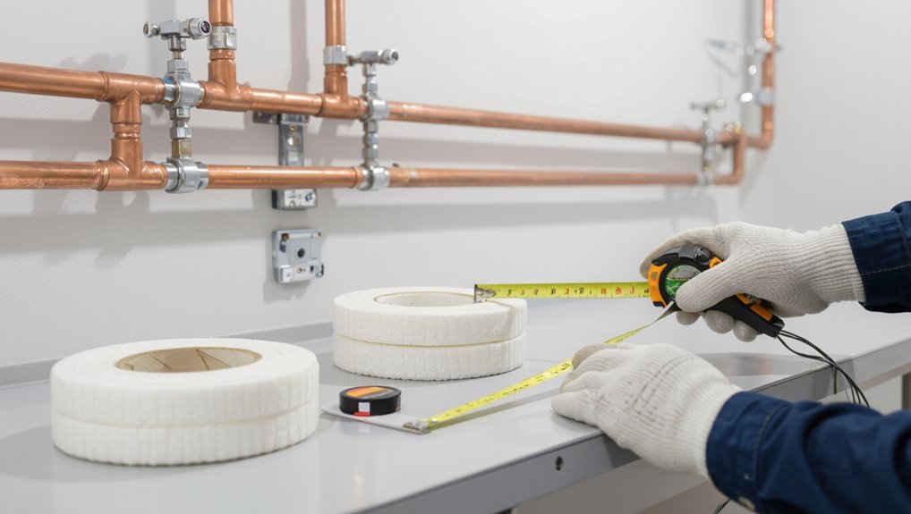
Accurate measurement guarantees insulation is sized to maximize energy efficiency and maintain safe surface temperatures.
Properly sized insulation reduces heat loss, lowers energy costs, and helps prevent condensation or scalding hazards.
Conversely, undersized insulation wastes energy and raises safety risks, while oversized insulation can be uneconomical and create installation challenges.
Benefits of correct sizing for energy efficiency and safety
When pipe insulation is measured and fitted to the correct dimensions, systems retain heat more effectively, reducing fuel or electricity consumption for heating and minimizing condensation on cold lines.
Proper sizing improves energy efficiency, lowers operating costs, and enhances system safety by stabilizing pipe temperatures and preventing surface hazards.
Accurate procedures, including how to measure pipe insulation, support regulatory compliance and long-term performance.
Common consequences of undersized or oversized insulation
Undersized insulation leads to increased heat loss, higher energy bills, and greater risk of condensation and corrosion, while oversized insulation can cause installation difficulties, increased material costs, and reduced accessibility for maintenance.
Incorrect sizing also shortens equipment life, impairs system performance, and elevates safety hazards. Proper measurement prevents thermal inefficiency, moisture issues, and unnecessary expense, ensuring reliable operation and manageable upkeep.
Quick answer: How to measure pipe insulation for sizing and heat loss
A quick summary: measure the pipe outer diameter, length of each run, and ambient conditions to select insulation thickness and estimate heat loss.
Simple runs and accessible pipes can usually be handled by a homeowner with a tape measure and insulation charts.
Consult a professional when pipes are concealed, in complex systems, or when precise heat-loss calculations are required for energy codes or HVAC sizing.
One-sentence summary of the measurement process
Measure the pipe’s outside diameter and length, note the fluid and operating temperatures, then use those values with insulation thickness charts or heat-loss formulas to select insulation size and verify thermal performance.
The practitioner records ambient conditions, surface emissivity, and desired temperature control. They apply standard thermal-resistance methods or manufacturer tables and confirm the chosen insulation meets heat-loss targets and safety or code requirements before installation.
When to call a professional
When should a professional be engaged to size pipe insulation and assess heat loss?
A professional is recommended for complex systems, concealed piping, high-temperature or hazardous fluids, code compliance, or when accurate heat-loss calculations affect system performance.
They guarantee proper measurement, material selection, and thermal modeling, reducing the risk of undersizing, condensation, or energy inefficiency.
Engage one if uncertainty or significant cost is involved.
Materials and tools required for measuring pipe insulation
Accurate insulation measurement begins with the right set of tools: tape measures, calipers, and laser distance meters for physical dimensions.
Thermal assessment requires infrared thermometers or thermocouples to record surface and fluid temperatures.
Reference materials—pipe specification charts and insulation manufacturer data—are essential for converting measurements into correct insulation thickness and heat-loss estimates.
Measuring tools (tape measure, calipers, laser distance)
A small set of reliable measuring tools—tape measure, calipers, and a laser distance meter—forms the foundation for sizing pipe insulation correctly.
The tape measures long runs and bend offsets; calipers measure external diameters and wall thickness precisely; laser distance meters verify runs in confined or elevated spaces.
Choose calibrated, durable tools and keep measurements recorded for accurate material selection and ordering.
Thermal tools (infrared thermometer, thermocouples)
Thermal tools such as infrared thermometers and thermocouples provide the temperature data necessary to evaluate insulation performance and locate heat losses.
Infrared thermometers offer quick surface readings and thermal imaging for patterns; thermocouples deliver accurate point temperatures for calculating gradients.
Both require proper emissivity settings, contact preparation, and calibration.
Use them to verify insulation effectiveness and identify areas needing repair or added thickness.
Reference materials (pipe specification charts, insulation manufacturer data)
Reference materials such as pipe specification charts and insulation manufacturer data provide the dimensional, thermal, and installation parameters essential for measuring and evaluating pipe insulation.
These references supply nominal pipe diameters, wall thicknesses, recommended insulation thicknesses, thermal conductivity (k-values), R-values, density, surface emissivity, and recommended fastening/closure methods.
They enable accurate sizing, heat-loss calculations, and compliance with codes and project requirements.
Identifying pipe type and conditions before measuring
Before taking measurements, one should identify the pipe material—copper, steel, PVC, or PEX—as different materials affect insulation choice and measurement technique.
The installer should note whether pipes are buried, exposed, already insulated, or run in bundles, since access and contact points vary.
Operating temperature and ambient conditions must be recorded to select appropriate insulation thickness and account for thermal expansion.
Distinguishing pipe material (copper, steel, PVC, PEX)
Because different pipe materials affect insulation choice and measurement approach, identifying whether a run is copper, steel, PVC, or PEX is a critical first step.
Visual inspection, magnetic testing, and weight or flexibility checks distinguish metals from plastics. Note fittings, markings, and corrosion.
Material determines thermal conductivity, maximum temperature, and suitable insulation types; record findings before measuring diameter and length.
Identifying buried, exposed, insulated, or bundled pipes
After identifying the pipe material, the next step is to determine whether the run is buried, exposed, already insulated, or bundled with other lines. Each condition changes access, measurement technique, and insulation choice.
Inspect visibility, proximity to walls or soil, sleeve or jacket presence, and number of parallel pipes. Note physical damage, fittings, and branching to plan measurement points and suitable insulation application.
Recording operating temperature and ambient conditions
Accurate measurement of pipe insulation requires recording the pipe’s operating temperature and the surrounding ambient conditions, since these values determine required insulation thickness, material selection, and expected heat transfer.
The technician documents steady and peak temperatures, surface temperature readings, fluid type, and flow if known.
Ambient air temperature, humidity, and exposure (indoor, outdoor, direct sunlight) are recorded to inform heat-loss calculations and material suitability.
Step-by-step guide to measure pipe diameter and circumference
The procedure begins with simple tape-measure readings for exposed single pipes, noting diameter directly across the pipe.
For wrapped, corroded, or hard-to-access pipes, calipers or a circumference-wrap method provide accurate alternatives, with bundled or closely spaced runs measured by isolating accessible segments or using flexible measuring tools.
Conversions between circumference and diameter are handled with the formula D = C/π (or C = πD) and quick reference values for common sizes.
Measuring exposed single pipes with tape measure
Measure the pipe’s diameter and circumference directly with a tape measure to determine the correct insulation size.
The technician wraps the tape snugly around the pipe midpoint to read circumference, then measures across for diameter.
Record measurements in millimeters or inches, note wall thickness if visible, and round to the nearest standard insulation size.
Repeat along run for consistency and variations.
Measuring wrapped or corroded pipes using calipers or circumference method
When pipes are wrapped or corroded, technicians rely on calipers or the circumference method to determine true diameters without removing coverings.
Calipers measure external diameter through gaps or over insulation edges. For circumference, a flexible tape encircles the pipe, recording length; diameter equals circumference divided by pi.
Record measurements twice, note irregular corrosion, and apply average values for insulation sizing and heat-loss calculations.
Measuring bundled or closely spaced pipes
In situations where pipes run tightly together or are bundled, technicians adapt caliper and circumference techniques to avoid disassembly. They measure accessible portions, note center-to-center spacing and bundle geometry, and record individual pipe exposure.
For inaccessible runs, they measure outer bundle dimensions and count pipes, then deduce each pipe’s effective perimeter from layout. All measurements are documented with locations and confidence levels for insulation sizing.
Converting circumference to diameter and vice versa (formula and quick references)
A simple mathematical relationship links a pipe’s circumference and diameter: circumference = π × diameter, so diameter = circumference ÷ π.
Using these formulas, technicians can convert a measured wrap or caliper reading into the other dimension quickly and accurately.
For practical use, keep a quick reference: C≈3.142×D and D≈0.3183×C.
Round to appropriate precision for insulation sizing and heat-loss calculations.
Determining required insulation thickness for thermal performance
Using the measured pipe diameter and operating temperature, the installer consults manufacturer or engineering charts to select a baseline insulation thickness.
Ambient and surface temperatures plus the target reduction in heat loss are then used to refine that choice for effective thermal performance.
Thickness is increased or specified differently for outdoor exposure, freeze protection, and high-temperature systems to meet durability and safety requirements.
Using pipe diameter and operating temperature to select thickness from charts
When selecting insulation thickness from manufacturer or standards charts, the installer matches the pipe’s outside diameter and the operating temperature to the chart’s grid to determine the required thermal resistance.
The selected thickness aligns with material conductivity and service conditions, yielding a thickness value that meets target heat loss or surface temperature limits.
Verify against installation constraints and available product sizes before ordering.
Considering ambient temperature, surface temperature, and desired heat loss reduction
Although pipe insulation selection often starts with diameter and operating temperature, determining the required thickness for thermal performance also depends on ambient temperature, allowable surface temperature, and the target reduction in heat loss. These three factors interact to set the thermal gradient and consequently the insulation resistance needed.
Engineers calculate required thermal resistance using ambient and surface temperatures, then convert to thickness via material conductivity, balancing cost and performance.
Adjusting thickness for outdoor, freeze protection, and high-temperature systems
Because environmental exposure and operational hazards change the heat transfer requirements, insulation thickness must be adjusted for outdoor placements, freeze protection, and high-temperature service.
Designers select thicker insulation and weatherproof jacketing outdoors to limit convective and radiative losses.
For freeze prevention, thickness plus trace heating guarantees surface temperature stays above freezing.
High-temperature systems need insulation to control heat loss, surface temperatures, and material limits.
Calculating heat loss for insulated pipes
Calculating heat loss for insulated pipes requires combining conduction through the insulation with convection and radiation at the outer surface to quantify total thermal transfer.
A clear, step-by-step procedure uses standard formulas for straight pipes—incorporating pipe and insulation diameters, temperature differences, insulation k-value, and surface heat transfer coefficients—to compute watts per metre.
Converting those heat losses into annual energy and cost estimates for representative hot water and steam lines illustrates the financial impact of insulation choices.
Heat loss basics: conduction, convection, and radiation
When evaluating heat loss from insulated pipes, three mechanisms—conduction through the insulation, convection from the outer surface to the surrounding fluid, and radiation to nearby surfaces—must be considered together because each controls a different stage of energy transfer.
Conduction governs movement within the insulation, convection sets the boundary-layer transfer rate, and radiation becomes significant at higher surface temperatures or in low-convection environments.
Conduction depends on thermal conductivity and thickness; convection on h and flow; radiation on emissivity and temperature difference.
Step-by-step heat loss calculation for straight pipes (formulas and inputs)
Having established how conduction, convection, and radiation jointly control heat transfer, the next step is to apply those mechanisms in a worked procedure for straight insulated pipes.
The method lists required inputs: pipe diameter, insulation thickness, pipe and ambient temperatures, pipe length, and flow conditions.
Use cylindrical conduction formula and convective loss on outer surface, compute per-meter heat loss, then total loss.
Accounting for insulation thermal conductivity (k-value) and surface coefficients
Accuracy in predicting heat loss for insulated pipes hinges on correctly accounting for the insulation’s thermal conductivity (k-value) and the surface heat-transfer coefficients that govern convection and radiation at the outer layer.
The k-value determines radial conductive resistance; outer surface coefficients (ho), combined with ambient conditions, set convective and radiative losses.
Use appropriate temperature-dependent k and measured or tabulated ho for accurate U-values.
Example heat loss calculations for hot water and steam lines
With the thermal conductivity and surface coefficients established, practical examples illustrate how those parameters convert into actual heat-loss rates for hot water and steam piping.
For a given pipe diameter, insulation thickness and temperatures, calculate radial conduction resistance and convective surface resistance.
Sum resistances to get overall U, then multiply by surface area and temperature difference to obtain watts or BTU/h for hot water and steam lines.
Converting heat loss to energy cost estimates
Translate calculated heat loss into monetary terms by converting energy lost per unit time into fuel or electricity consumption and then applying local energy prices and system efficiencies.
Multiply watts or BTU/hr by hours to get kWh or therms, adjust for boiler or heater efficiency, then multiply by unit cost.
Include demand charges and maintenance allowances for annualized, comparative cost estimates to justify insulation upgrades.
Special cases and corrections
Special cases and corrections address elements that standard pipe measurements miss, such as valves, flanges, fittings, and unions, which require individual measurement and customized insulation shapes.
The guidance also covers methods for runs that are insulated, partially accessible, buried, or routed through ducts, including how to account for altered heat-loss profiles.
Corrosion under insulation is treated as both an inspection priority and a factor that can change measurement assumptions and remediation needs.
Measuring and insulating valves, flanges, fittings, and unions
Valves, flanges, fittings, and unions require individualized measurement and treatment because their irregular shapes and varied orientations interrupt continuous insulation runs and create thermal bridges.
Measure each component’s maximum cross-section and depth, note connection types and access needs, and select matching insulation jackets, removable covers, or molded pieces.
Account for additional thickness at joints and use sealing tapes or gasketing to maintain continuity and minimize heat loss.
Handling insulated or partially accessible runs
After measuring irregular components like valves and flanges, attention must turn to runs that are already insulated or only partially accessible.
Inspect exposed ends and record existing insulation thickness and condition. Measure accessible lengths and document concealed segments with sketches and notes.
Estimate hidden dimensions using system drawings or thermal imaging. Apply conservative allowances and mark areas needing removal or repair before final calculations.
Insulating buried or ducted piping
Many buried or ducted piping runs require adjustments to standard measurement methods because access, moisture, and surrounding materials alter insulation needs.
Measure buried runs by excavating representative sections or using as-built drawings; account for soil thermal resistivity, bedding, and drainage.
For ducts, include clearance, supports, and airflow impact.
Specify vapor barriers, appropriate insulation type, thickness, and installation details for confined spaces.
Corrosion under insulation: inspection and measurement implications
Addressing corrosion under insulation (CUI) requires integrating inspection findings with measurement adjustments, since hidden corrosion affects required insulation upkeep and replacement decisions.
Inspectors should record localized wall loss, pitting, and coating failures; adjust insulation thickness and material selection to permit drying and future access; factor repair delays into heat-loss models; and document locations for routine monitoring and targeted remediation to prevent recurrence.
Choosing insulation type and installation considerations
Choosing the appropriate insulation—such as foam, fiberglass, or elastomeric—depends on thermal performance, moisture resistance, and application temperature.
Attention must be paid to weatherproofing, vapor barriers, and jacketing to protect the insulation and prevent degradation.
Proper installation practices, including correct fit, sealing of seams, and support spacing, are required to guarantee the measured performance matches design expectations.
Common insulation materials and their properties (foam, fiberglass, elastomeric)
When selecting insulation for pipes, assess the operating temperature, moisture exposure, and space constraints to determine whether foam, fiberglass, or elastomeric materials are most appropriate.
Closed-cell foam offers low thermal conductivity and moisture resistance for moderate temperatures.
Fiberglass tolerates higher temperatures but requires vapor control and careful handling.
Elastomeric rubber provides flexibility, condensation prevention, and durable performance in variable environments.
Weatherproofing, vapor barriers, and jacketing options
Effective weatherproofing and vapor control are critical for preserving pipe insulation performance and preventing moisture-related damage.
Selection among vapor retarders, taped seams, and impermeable jacketing depends on climate, exposure, and pipe temperature.
Metal, PVC, or aluminum jacketing shields insulation outdoors; vapor barriers prevent condensation and mold.
Properly matched materials extend life, maintain R-value, and reduce corrosion under insulation risk.
Installation best practices to maintain measured performance
Having selected proper weatherproofing and vapor control, attention shifts to installation practices that preserve the insulation’s rated thermal performance.
Installers must fit insulation tightly around fittings, maintain continuous vapor barriers, and seal joints with compatible tapes or mastic.
Support spacing should prevent compression, and surface finish must resist UV and mechanical damage.
Regular inspection and correct fastening guarantee long-term thermal integrity.
Common errors and how to avoid them
Common errors in pipe insulation begin with measurement mistakes that lead to incorrect sizing and gaps.
Misapplied formulas and overlooked variables produce heat loss calculations that are either optimistic or overly conservative.
Practical steps—double-checking diameters and wall thickness, using calibrated tools, and verifying heat-loss inputs—reduce these risks.
Measurement mistakes that cause incorrect sizing
Mistakes during pipe insulation measurement often stem from skipped steps, incorrect tool use, or assumptions about pipe layout; these errors lead to undersized or oversized insulation that compromises thermal performance and increases costs.
Common faults include measuring around bends incorrectly, ignoring fittings and joints, misreading tape measures, and failing to record pipe material or diameter variations.
Verifying measurements and documenting conditions prevents sizing errors.
Calculation pitfalls for heat loss estimates
Several recurring errors undermine heat loss estimates for insulated piping, often stemming from incorrect assumptions about surface temperatures, neglecting conductive gaps at joints, using inappropriate convective coefficients, or applying steady-state formulas to transient conditions.
Other pitfalls include misreading material thermal conductivities, ignoring buried or wind-exposed conditions, and rounding intermediate values excessively; each distorts results unless validated against measured temperatures and consistent boundary assumptions.
Practical tips to improve measurement accuracy
Having identified typical calculation pitfalls, attention now turns to practical tactics that reduce measurement error and improve confidence in heat-loss assessments.
Use calibrated instruments, measure multiple points along runs, record ambient and surface temperatures, and note insulation gaps, fittings, and wet or compressed sections.
Cross-check pipe diameters against drawings, document measurement methods, and apply conservative assumptions where uncertainty persists to avoid underestimating heat loss.
Tools and templates to streamline measurement and calculation
Practical tools and ready-made templates reduce measurement errors and speed up insulation specification.
The following items cover essential resources to use in the field and office:
- Printable measurement checklist and data sheet
- Recommended apps and calculators
- Sample lookup tables for quick diameter-to-thickness selection
Printable measurement checklist and data sheet
A printable measurement checklist and data sheet consolidates essential fields—pipe diameter, insulation type and thickness, linear footage, fittings count, temperature range, and measurement date—so technicians can capture consistent inputs on-site.
The sheet includes space for notes, photos references, material codes, and project ID.
Preformatted calculation rows and a signature/date line guarantee traceability and handoff readiness for accurate insulation ordering and verification.
Recommended apps and calculators
Several mobile apps and web-based calculators simplify on-site pipe insulation measurement and material estimation by converting raw measurements into required insulation lengths, surface areas, and volume-based material needs.
Recommended tools offer pipe circumference/diameter inputs, insulation thickness selection, thermal conductivity libraries, and heat-loss calculators. They export reports, material lists, and cost estimates, support metric/imperial units, and reduce manual errors for faster, consistent project documentation and bidding.
Sample lookup tables for quick diameter-to-thickness selection
Lookup tables present a concise reference that maps common pipe diameters to recommended insulation thicknesses based on factors like operating temperature, exposure conditions, and energy-code requirements. They enable rapid selection, reduce calculation errors, and support documentation. Use tables alongside project specifics and verify against codes.
| Pipe OD (in) | Temp range (°F) | Thickness (in) |
|---|---|---|
| 0.5–1.0 | 32–150 | 0.5 |
| 1.25–2.0 | 32–300 | 1.0 |
| 2.25–4.0 | 32–400 | 1.5 |
| 4.5–8.0 | 32–400 | 2.0 |
When to consult codes and standards
Brief reference to relevant standards and building codes helps guarantee insulation thickness, material selection, and fire or energy requirements are met.
Professionals should record measurements and the code references used so installations can be verified during compliance checks and audits.
When project scope or jurisdictional rules are unclear, a formal review of applicable codes should precede final specification.
Relevant standards and building codes for pipe insulation
When determining pipe insulation requirements, consulting relevant standards and building codes guarantees compliance with safety, energy efficiency, and fire-protection objectives.
Applicable documents include national energy codes, plumbing and mechanical codes, fire safety standards, and industry specifications (e.g., ASME, ASTM, ISO).
References dictate minimum R-values, vapor barriers, clearance to combustibles, and material approvals; contractors should verify jurisdictional amendments and project-specific requirements.
Documenting measurements for compliance and audits
After identifying the applicable codes and standards, the documentation of pipe insulation measurements becomes the primary record for demonstrating compliance during inspections and audits.
Records should include measurement dates, personnel, locations, pipe diameters, insulation type and thickness, calculation methods, and referenced standards.
Photographic evidence, calibrated tool logs, and versioned reports guarantee traceability and support corrective actions or regulatory reviews.
Final verification and maintenance
After installation, the insulation is inspected to confirm proper fit and required thickness along the entire run.
A schedule for periodic checks and re-measurements is established to detect settling, damage, or degradation.
Findings are documented in a maintenance log to support long-term energy management and future audits.
Inspecting installed insulation to confirm fit and thickness
Inspect the installed insulation visually and with simple tools to verify that it fits snugly against the pipe, maintains the specified thickness, and shows no gaps, compressions, or damage that would reduce thermal performance.
Confirm seam closure, secure fastenings, and intact vapor barriers. Measure thickness at representative points with calipers or a depth gauge, record deviations, and note areas requiring repair or immediate corrective action.
Periodic checks and re-measurement schedule
Establish a regular schedule of periodic checks and re-measurements to guarantee insulation continues to meet performance specifications and to catch degradation early.
Frequency should reflect service conditions—annually for stable systems, more often for harsh environments.
During each check, verify thickness, surface condition, seams, and moisture intrusion.
Record deviations, prioritize repairs, and retest after corrective actions to confirm restored performance.
Recordkeeping for long-term energy management
Effective recordkeeping forms the backbone of long-term energy management by providing verifiable data for final verification and ongoing maintenance decisions.
Records should log insulation measurements, materials, installation dates, thermal performance, and corrective actions.
Use standardized digital formats, timestamped photos, and versioned reports to enable trend analysis, warranty claims, and regulatory compliance.
Secure backups and access controls preserve integrity and support objective performance reviews over time.
Practical examples and case studies
The section presents concise case studies illustrating measurement techniques and outcomes for three common situations.
First, a residential hot water line example shows how to measure, size insulation, and estimate heat loss.
Next, a commercial chilled-water case highlights measurement challenges and solutions, followed by a retrofit scenario demonstrating replacement of damaged insulation and recalculation of performance.
Residential hot water line: measurement, sizing, and heat loss example
A practical example follows that walks through measuring and selecting insulation for a typical residential hot water supply line, then quantifies heat loss to show how insulation choices affect energy use.
A 3/4″ copper pipe, 20 m run, 60°C supply, 20°C ambient is measured.
With 13 mm foam versus 25 mm fiberglass, calculated U-values and heat loss rates demonstrate energy savings and payback estimates.
Commercial chilled-water pipe: measurement challenges and solutions
Several common factors complicate measuring commercial chilled-water piping: long runs with multiple insulation types, buried or ceiling-concealed segments, variable pipe diameters and fittings, and surface condensation risks that affect sensor placement and readings.
Practical solutions include mapping runs, using non-invasive ultrasonic or infrared tools, recording insulation thickness at intervals, documenting fittings and valves, and applying conservative thermal conductivity values for mixed materials to estimate heat loss accurately.
Retrofit scenario: replacing damaged insulation and re-calculating performance
Begin by evaluating the affected run to establish baseline conditions: note original insulation type and thickness, extent and locations of damage, pipe diameter changes, and surrounding environmental factors such as ambient temperature and humidity. The team documents losses, selects replacement material matching or improving R-value, recalculates heat loss, and verifies by spot measurements and thermal imaging.
| Item | Observation |
|---|---|
| Damage | Localized corrosion |
| Action | Replace with closed-cell foam |
| Result | 18% reduced heat loss |
Conclusion
Accurate pipe insulation measurement guarantees energy efficiency, safety, and code compliance, tying system performance and lifecycle costs together like a well-calibrated clock. The guide’s stepwise approach—identifying pipe type, using calipers or tapes, calculating circumference and required insulation thickness, and referencing standards—reduces error and simplifies maintenance planning. Final verification and periodic checks preserve insulation integrity and system efficiency, while case studies illustrate real-world application and common pitfalls for practitioners.