How to Bend Pipe: Easy DIY Guide for Smooth, Accurate Bends
To bend pipe smoothly and accurately, choose the right tool and technique based on the material and size of the tube. Here are key takeaways for successful pipe bending:
- Measure and Mark: Start by measuring and marking the centerlines and accounting for bend allowance and setback.
- Secure the Tube: Use soft jaws or saddles to hold the tube firmly in place.
- Internal Support: For thin-walled pipes, incorporate internal support like spring, sand, or a mandrel to prevent collapsing.
- Choose the Right Die or Roller: Select the appropriate bending die or roller for your specific pipe.
- Apply Steady Pressure: Bend the pipe with consistent, even pressure and keep an eye on the angle as you work.
- Inspect for Quality: After bending, check for kinks or ovality, and if needed, make careful adjustments to correct any issues.
Following these steps will help you achieve precise and clean bends in your pipe bending projects.
What You’ll Be Able to Do After This Guide
After completing this guide, the reader will be able to select the proper bending method and tools for common pipe materials, measure and mark bend locations accurately, execute smooth, consistent bends without kinking, and restore pipe dimensions as needed for tight fittings.
The guide explains material-specific techniques, tool selection criteria, and basic safety precautions. It outlines how to calculate bend allowance and set up supports to maintain alignment.
It distinguishes when to bend versus when to use fittings, and describes methods to verify angles and fit before final installation.
The outcome is improved efficiency, reduced waste, and reliable, leak-free joints.
How to Bend Pipe: Quick Step‑by‑Step
With the fundamentals and selection criteria covered, the quick step‑by‑step shows how to bend pipe efficiently and safely.
First, measure and mark bend locations; allow springback.
Secure the pipe in a vice or bender with proper support.
Insert internal mandrel or filler if required.
Heat the bend zone evenly for malleable metals, avoiding overheating.
Apply steady pressure using a calibrated bender or follow prescribed leverage for hand tools, maintaining alignment.
Monitor angle with a protractor or jig.
Cool gradually, quench only if specified.
Remove supports, deburr cut edges, and inspect for kinks, cracks, or ovality before final fitting.
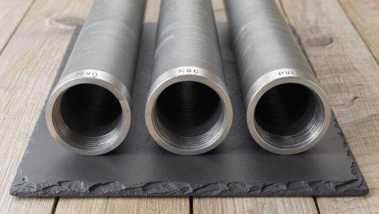
Which Pipes You Can Safely Bend at Home
The section outlines which pipe types are suitable for home bending, distinguishing common bendable materials such as copper, annealed steel, and PEX.
It highlights typical wall thickness and diameter limits that affect whether a pipe can be formed without kinking or splitting.
It also summarizes essential safety and preparation steps, including proper support, heating where appropriate, and personal protective equipment.
Types Of Bendable Pipes
When considering which household pipes can be safely bent, attention focuses on material, wall thickness, and purpose; copper, annealed steel, polyethylene (PEX), and soft copper-clad aluminum are commonly bendable by hand or with simple tools, while rigid materials like PVC and thick-walled steel require specialized equipment or replacement fittings. Common bendable types: soft copper for plumbing curves, PEX for flexible runs, and annealed steel for light HVAC or automotive work. Match tool choice to pipe type and intended system. Table summarizes typical bendable options.
| Pipe Type | Common Use | Bendability |
|---|---|---|
| Copper | Water lines | High |
| PEX | Domestic plumbing | Very High |
| Annealed steel | Light mechanical | Moderate |
Materials And Thickness Limits
Having identified common bendable pipe materials, attention turns to the material properties and wall thickness that determine whether a pipe can be bent safely at home.
Soft copper and annealed aluminum with thin to moderate walls (Type L or M copper, 0.5–3 mm aluminum) bend readily with handheld tools. Steel requires thinner-walled tubing (cold-drawn low-carbon, thin-wall ERW) and often larger radii; thick-walled or high-carbon steel resists forming and risks cracking.
PVC and CPVC are limited by brittle behavior unless heated and require careful thickness control. Wall thickness, alloy, temper, and intended-for bend radius together dictate feasibility; consult manufacturer specs before attempting bends.
Safety And Preparation Tips
Typically, homeowners can safely bend only soft, thin-walled metals—like annealed copper (Type L or M), thin aluminum tubing, or low-carbon cold-drawn steel—while avoiding thick, high-carbon steel, rigid plastics, and any pipe with unknown alloy or temper.
Inspect pipe for corrosion, welds, or cracks; defects increase fracture risk. Use correct mandrel, spring, or filler to prevent kinks.
Measure and mark bend location; allow workroom ventilation and clear floor space.
Wear gloves, eye protection, and hearing protection for powered tools.
Secure pipe in a vise or bender.
If unsure of material or safety, consult a professional or supplier before bending.
When to Replace Instead of Bending Pipe
Although bending can salvage many runs of pipe, replacement becomes necessary when damage, material limits, or code constraints compromise safety or function.
Corrosion, cracks, severe dents, or previous welds can weaken integrity; bends may worsen leaks or collapse. Certain alloys and thin‑wall tubing cannot accept safe radii. Codes or inspection requirements sometimes mandate new sections after alteration.
Cost and time to repair complex defects often exceed replacement. A pragmatic assessment weighs remaining service life, pressure ratings, and access for future maintenance.
When safety, compliance, or long‑term reliability are doubtful, full replacement is the prudent choice.
- Visible corrosion pitting or through‑wall defects
- Cracks, splits, or crazing near bend zones
- Materials rated below required pressure or flexibility
- Code/inspection requirements forbidding field alteration
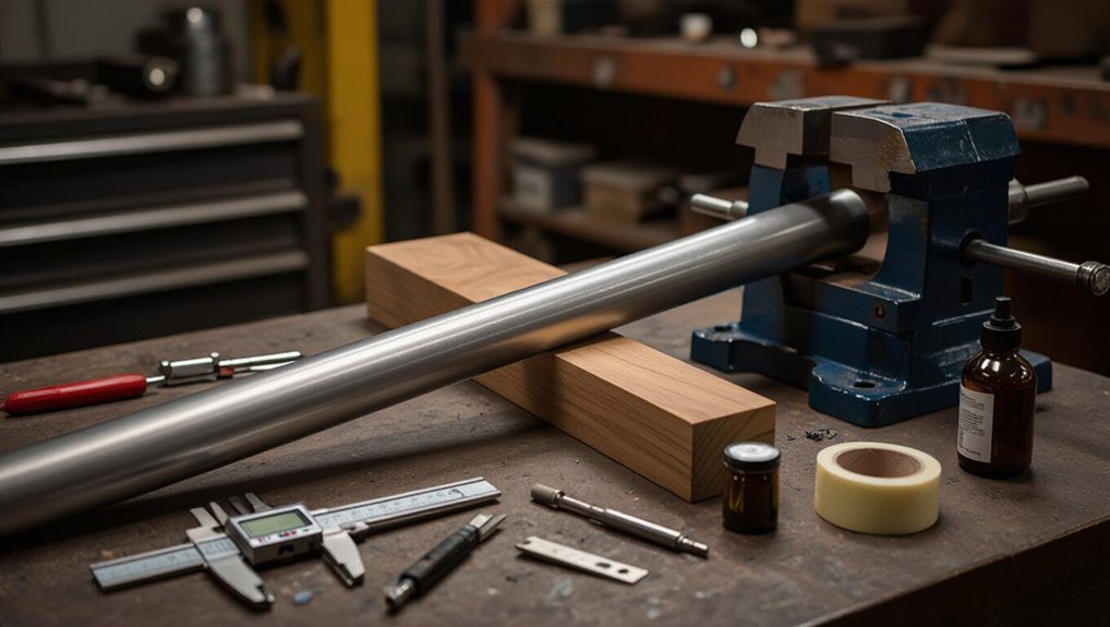
Essential Tools for Accurate Pipe Bends
Selecting the correct bender guarantees the pipe material and bend radius match the job requirements.
Accurate measuring and precise marking establish bend locations and angles before any tool is engaged.
Together, the right bender and careful layout reduce rework and maintain system integrity.
Choosing The Right Bender
When preparing for a bending job, choosing the right bender depends on pipe material, diameter, wall thickness, and required bend radius; these factors determine whether a manual hand bender, a spring bender, a hydraulic machine, or a rotary draw bender will deliver accurate, repeatable results. Selection favors simplicity for softer, small-diameter tubing and power for thick-walled or large-diameter pipes. Consider setup time, required accuracy, and springback control. Portability versus shop-installed capacity matters. Matching tooling (dies, shoes) to pipe profile prevents deformation and maintains flow.
- Manual hand bender: light gauge, portable
- Spring bender: thinwall tubing, quick jobs
- Hydraulic machine: thickwall, high force
- Rotary draw: precision, repeatability
Measuring And Marking
After the proper bender and tooling are chosen, accurate measuring and marking establish the positions and angles that will determine fit and function. The technician selects a reliable tape measure, calipers, angle finder, and a fine-tip marker or scribe. Measurements account for bend allowance, take-up, and setback; templates or jig references reduce error.
Marks are placed on the outside and inside of the pipe as required, with reference lines parallel to the axis for rotational alignment. Double-checking critical dimensions and transferring marks to the bender frame prevents misalignment. Clear, consistent marking speeds setup and guarantees repeatable, accurate bends.
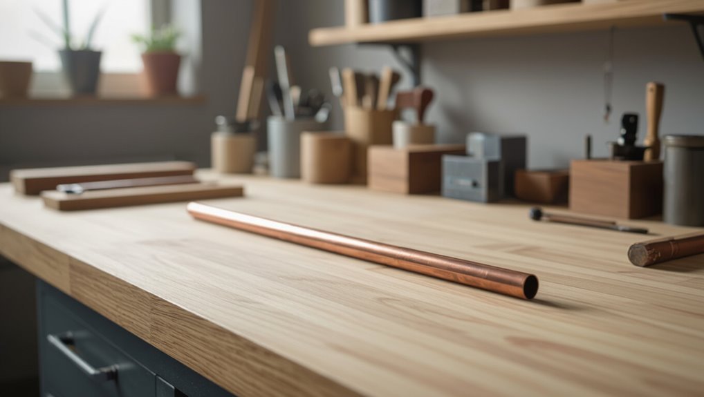
Affordable Tool Alternatives for DIYers
For DIYers on a budget, practical alternatives to expensive pipe-bending equipment make small plumbing or metalwork projects attainable without sacrificing safety or results.
A few simple tools and techniques enable controlled bends for copper, aluminum, and thin-walled steel. Careful preparation—cleaning, annealing softer metals, and supporting the pipe—reduces kinks.
Using clamps, templates, and slow steady force gives repeatable results. Projects requiring complex or heavy-gauge work should still consult professionals.
- Spring or silicone-filled tube for stabilizing and bending soft metal
- Bench vise with protective jaws for gradual forming
- Sand or concrete-filled pipe as an internal mandrel
- Wooden formers and a mallet for gentle shaping
Choose the Right Bender: Material, Size, Budget
In selecting a pipe bender, the buyer should match the tool to the metal type, pipe diameter, and project scope: lightweight hand benders suit soft metals and small diameters, tubing benders with die sets handle precise bends in copper and aluminum, while hydraulic or ratcheting benders are necessary for thicker-walled steel and larger sizes.
Consider bender capacity ratings, required bend radius, and available dies. Portability, durability, and maintenance affect value. Compare manual, electric, and hydraulic options against expected frequency and precision needs. Balance upfront cost with longevity; renting specialized machines can be economical for occasional heavy work.
How Pipe Material Affects Bendability
Selecting the correct bender only solves part of the problem; the metal being formed dictates how a pipe will respond during bending. Different alloys have distinct ductility, yield strength, and work-hardening behavior, which determine springback, cracking risk, and required bend force. Corrosion-resistant metals, heat-treated alloys, and softer metals each demand tailored approaches.
- Aluminum: highly ductile but prone to wrinkling without internal support.
- Copper: very malleable, allows tight bends with minimal tooling.
- Stainless steel: strong, resists deformation, exhibits significant springback.
- Mild steel: forgiving, balances strength and formability for most DIY jobs.
Wall Thickness, OD, and Minimum Bend Radius
When bending pipe, wall thickness and outside diameter (OD) directly govern how sharply a tube can be formed without collapsing, wrinkling, or cracking; together they determine the minimum bend radius and the amount of mandrel support, die profile, and bend force required.
Thicker walls and larger OD increase stiffness, permitting smaller radii relative to diameter but requiring greater force and sturdier tooling.
Thin‑walled or small‑OD tubing needs larger bend radii, internal support, or gradual bends to avoid deformation.
Manufacturers specify minimum bend radius (often as multiples of OD).
Accurate measurement and conservative selection prevent failures and reduce springback and wrinkling.
Common Bend Types: Offset, 90°, U, and Sweep
Frequently, pipe bending tasks call for a small set of standard shapes—offsets, 90° bends, U‑bends, and sweeps—because each addresses distinct routing and clearance needs: offsets shift a run laterally, 90° bends change direction sharply, U‑bends reverse flow with compact geometry, and sweeps provide gradual curvature for smooth flow or aesthetic continuity.
Selection depends on space, flow and attachment points.
Each type has predictable tooling and setup: offsets use paired bends, 90° requires accurate angle control, U‑bends need consistent leg spacing, and sweeps demand longer mandrels or larger radii.
- Offset: two opposing bends to clear obstacles
- 90°: tight directional change
- U‑bend: return or compact loop
- Sweep: gentle, continuous curve
How to Measure and Mark Bend Locations
The technician measures twice to make certain precise placement before any bending begins.
Bend centers are marked clearly on the pipe to align with the bender and fixtures.
Bend allowance is calculated and accounted for so the final fit matches the layout.
Measure Twice Precisely
Before any bending begins, the pipe is measured and marked with exactness: locations for each bend are determined from fixed reference points, accounting for material springback, fitting overlap, and any relief cuts.
Measurements are verified twice, using a calibrated tape and a rigid rule, with marks transferred around the pipe circumference for alignment.
Distances are noted relative to ends and junctions; tolerance limits are recorded.
Marks are made with non-permanent, high-contrast indicators so adjustments remain possible.
The process emphasizes consistent reference use and rechecking after any repositioning to prevent cumulative error.
- Calibrated tape and rigid rule used
- Circumferential alignment marks
- Recorded tolerances and offsets
- Non-permanent high-contrast indicators
Mark Bend Centers
Locate each bend center by measuring from established reference points and transferring those measurements onto the pipe with a clear, single center mark. Use a rigid tape or calipers and square the measurement around the pipe, marking a small cross or dot at the circumference.
For multiple bends, label marks sequentially to prevent confusion. Confirm each mark against the template or drawing before proceeding.
When marking, account for pipe orientation so the bend will align in the correct plane; indicate rotation with a short line or arrow. Re-check measurements once marked to make certain consistency and avoid cumulative placement errors.
Account For Bend Allowance
When accounting for bend allowance, measurements must reflect the material stretch and compression that occur through bending so mark points on the pipe correspond to the finished dimensions rather than the flat layout.
The technician calculates the neutral axis shift, adds or subtracts the allowance from the developed length, and transfers marks to the pipe surface. Use consistent units, note bend angle and radius, and recheck calculations before cutting. Accurate marking prevents rework and poor fit.
- Determine bend angle, radius, and wall thickness
- Calculate allowance using standard formulas or charts
- Measure from reference end to each bend mark
- Verify marks with a template or test bend
Simple Bend Allowance and Take‑Up Calculation
In calculating simple bend allowance and take-up, the fabricator determines how much material is consumed by the bend so straight lengths can be cut accurately. The method uses inside radius, bend angle, and material thickness to estimate neutral axis length. A common approximation: BA = (π/180) × (R + K×T) × θ, where K is neutral axis factor (typically 0.3–0.5). Take-up equals half the difference between total straight length and developed arc per bend. Simple tables or calculators speed layout and reduce error.
| Variable | Typical Use |
|---|---|
| R | Inside radius |
| T | Wall thickness |
| θ | Bend angle |
How to Clamp and Support Pipe Before Bending
Before bending begins, the pipe must be secured with supports and clamps that hold its axis steady while allowing controlled movement at the bend. The workpiece rests on saddles spaced to prevent sag; clamps engage without deforming the tube. Fixed and sliding supports define the bend zone; a backup form or block prevents ovaling. Positioning aligns mark lines with the bending die and leaves room for the bender’s shoe. Inspect clamp pressure and support spacing before each stroke to avoid shifting or localized stress.
- Pipe saddles under neutral axis
- Soft-jaw clamps at hold points
- Sliding support at bend start
- Backup form against free end
Cold‑Bend Technique for Soft Copper and Aluminum
With the pipe secured on saddles and the clamps checked, the cold‑bend technique for soft copper and aluminum proceeds using controlled hand or mechanical force to form the curve without heating.
The operator marks the bend location, measures springback allowance, and supports the run to prevent twist.
Bending slowly maintains wall integrity; small incremental deflections reduce ovalization.
Internal mandrels or spring inserts may be used for very soft alloys to preserve cross‑section.
Frequent inspection for kinks and dimensional checks against a template guarantee accuracy.
After bending, relieve clamps gradually and deburr ends as needed before final installation.
Bend Pipe With a Manual Bender: Step‑by‑Step
The section outlines a straightforward manual-bender workflow beginning with selecting a bender sized to the pipe material and diameter.
It then covers precise measurement and marking to locate each bend.
Finally, it describes making slow, controlled bends while checking angle and alignment.
Choose The Right Bender
When selecting a manual pipe bender, prioritize the pipe material, diameter, and required bend radius to guarantee the tool matches the job’s demands. The right bender prevents kinking, secures consistent bends, and reduces effort.
Consider roller versus form benders, carriage length for leverage, and die sets for specific profiles. Inspect build quality, mounting options, and available accessories that match tube or conduit types. Match capacity ratings to wall thickness and alloy. Confirm portability needs versus shop permanence.
- Material compatibility (steel, copper, aluminum)
- Maximum diameter and wall thickness
- Bend radius and die availability
- Mounting and leverage options
Measure And Mark Pipe
Before bending, measure and mark the pipe precisely to make certain the bend lands at the correct location and angle.
The technician verifies overall length, accounts for compression or springback, and locates the neutral axis relative to fittings.
Using a reliable tape, square, and scribe, the operator marks the centerline of the planned bend and reference points for degree increments.
Marks should be thin, visible, and non-obstructive to the bender saddle.
If multiple bends are required, establish a baseline and sequence marks to preserve spacing.
Double-check measurements before setup to prevent waste and guarantee the final assembly aligns.
Make Controlled Bends
With measurements and marks confirmed, the operator positions the pipe in the manual bender so the centerline mark aligns with the bender’s pivot point and reference gauge.
The operator applies steady, even pressure to the handle, watching the degree indicator and any witness lines. Small adjustments and pauses prevent springback and kinking; back off slightly if resistance spikes.
Release the handle gradually at the target angle, then remove the pipe and compare the bend to the template. If fine-tuning is needed, reinsert and creep the bend in small increments to avoid overbending.
- Steady, even handle pressure
- Watch degree indicator
- Pause to prevent kinks
- Gradual release and check
Use a Spring or Internal Mandrel for Thin‑Wall Pipe
To prevent collapse and wrinkling in thin‑wall pipe during bending, a spring or internal mandrel provides internal support that maintains the tube’s shape and distributes bending stresses.
A removable compression spring fits inside the curve to resist ovalization for gentle bends and simple tooling.
For tighter radii or critical finishes, a segmented or solid mandrel offers continuous support, preventing wrinkles and reducing wall thinning.
Selection depends on tube diameter, wall thickness, bend radius, and tooling clearance.
Install the mandrel snugly, align its plugs with the bend center, and withdraw carefully after forming to preserve geometry and interior surface integrity.
When to Heat Steel: Strategy and Safety
The decision to apply heat to steel during pipe bending hinges on wall thickness, alloy, and required bend radius. Proper timing and controlled temperature reduce cracking and springback, while strict safety measures—heat shields, PPE, and clear work zones—protect operators.
The following section outlines when heating is necessary, how to time it, and essential safety practices.
When To Heat
When should a pipe be heated before bending depends on its material, wall thickness, and the required bend radius: mild steel with thin walls often bends cold, while thicker sections or large-angle, tight-radius bends typically require controlled heating to prevent cracking or ovality.
Heat is used when cold forming would overstress the metal, when springback must be reduced, or when reducing wall thinning during tight-radius bends.
Heating should be localized and uniform.
Indicators for heating include visible cracking risk, severe springback, very tight radii, or material specifications calling for preheat.
- Thin-walled mild steel: usually cold
- Thick sections: consider heat
- Tight-radius bends: favor heating
- Specified alloys: follow preheat requirements
Safety And Timing
Occasionally, operators must pause and assess both timing and safety before applying heat for a steel bend: proper sequencing—when to preheat, how long to soak, and when to allow controlled cooling—directly affects metal behavior and worker risk.
Personnel should use thermal markers, calibrated torches, and contact thermometers to reach target temperatures without overheating. Ventilation, flame-resistant PPE, and clear exclusion zones reduce injury.
Soak times depend on section thickness and alloy; insufficient soak causes cracking, excessive soak alters microstructure. Controlled cooling prevents warping.
Record temperatures and durations for repeatable results. When uncertain, consult material datasheets or a metallurgist before proceeding.
How to Bend Steel Pipe Safely With Heat
Heat can be applied to steel pipe to increase ductility and allow controlled bending without cracking or collapsing the wall.
The procedure requires clean pipe, measured heating, and steady bending to maintain radius and wall integrity.
Use a propane or oxy-acetylene torch to heat the bend area evenly, watch temperature color or use an infrared thermometer, and support the pipe to prevent ovalization.
Allow slow, controlled cooling or quench per material needs.
Wear PPE and keep fire safety gear ready.
- Even, localized heating along the bend length
- Firm, gradual bending with proper supports
- Temperature monitoring and controlled cooling
- Fire suppression and PPE ready
What to Expect From Hydraulic and Electric Benders
In comparing hydraulic and electric benders, users should expect differing trade-offs in force delivery, speed, and control: hydraulic units provide high torque and smooth, powerful strokes suited for thick-walled or large-diameter pipe, while electric benders offer faster setup, cleaner operation, and better suitability for lighter pipe and repetitive shop work.
Hydraulic machines excel at heavy-duty, slow, controlled bends with predictable backpressure and require maintenance for fluid systems. Electric models deliver consistent cycle times, quieter operation, and easier mobility but may stall on very stiff sections.
Choice depends on material, production volume, portability needs, and available power sources.
Conduit vs. Plumbing Pipe: Bending Differences and Codes
After weighing hydraulic versus electric benders for force and control, attention turns to the distinct requirements of conduit and plumbing pipe bending.
Conduit (EMT, rigid) demands consistent radius and electrical code compliance: maintain fill capacity, avoid damage to insulation, and use specified bending tools.
Plumbing pipe (copper, PEX, PVC) emphasizes flow, joint integrity, and pressure ratings; some materials require heat or specialty fittings.
Inspect fittings, follow local electrical and plumbing codes, and verify permitted bend counts and radii.
Use proper supports and test assemblies for leaks or continuity before concealment.
- Conduit: tight, uniform radii per NEC
- Copper: anneal for sharp bends
- PEX/PVC: use bends or fittings as allowed
- Verify local code and inspector requirements
How to Avoid Flattening, Kinking, or Wrinkling
To prevent flattening, kinking, or wrinkling, the technician must begin with proper internal support sized to the pipe and material.
Maintaining an appropriate bend radius and using tooling that matches that radius reduces stress and deformation.
Applying slow, even pressure throughout the bend guarantees the pipe conforms smoothly without collapsing.
Use Proper Internal Support
When bending pipe, providing correct internal support prevents flattening, kinking, and wrinkling by maintaining the tube’s circular cross-section and distributing stresses evenly along the bend.
Internal supports such as mandrels, sand, or polyurethane plugs fill the lumen, resist inward collapse, and guide material flow.
Selection depends on pipe diameter, wall thickness, and bend method; removable mandrels suit tight bends, sand is economical for gentle curves, and expandable plugs work for varied sizes.
Proper placement and secure retention avoid movement during bending, ensuring uniform wall thickness and a smooth, usable bend without compromising structural integrity.
- Solid mandrel sized to fit lumen
- Granular sand packed and sealed
- Expandable polyurethane plug
- Tailstock support or drift tool
Control Bend Radius
In bending pipe, maintaining an appropriate bend radius is essential to prevent flattening, kinking, or wrinkling by keeping material stresses within allowable limits and preserving the tube’s cross-section.
The correct radius depends on tube OD, wall thickness, and material ductility; manufacturers specify minimum bend radii.
Tight radii concentrate compressive and tensile strains, causing collapse on the intrados and splitting on the extrados.
Select tooling that matches the intended-to-be radius and use mandrels or internal supports sized to maintain ID spacing.
For unfamiliar alloys, test short samples and measure cross-section and ovality to confirm acceptable deformation before final work.
Slow, Even Pressure
Typically, operators apply slow, even pressure throughout a bend to keep strains distributed and prevent localized collapse or wrinkles.
The technician advances steadily, monitoring curvature and listening for signs of metal stress.
Slow motion allows internal grain and wall thickness to adjust without sudden deformation.
Visual checks and tactile feedback guide incremental progress, while heat or internal supports compensate when needed.
Consistent rhythm minimizes springback and maintains roundness.
- Hand-feed with measured increments to avoid sudden compression
- Use a mandrel or sand fill for thin-walled tubes
- Pause to inspect for flattening or sharp creases
- Apply heat only where controlled and uniform
Fixes for a Slightly Crushed or Kinked Bend
Slightly crushed or kinked bends can often be restored without replacing the pipe by carefully reshaping the damaged section to recover flow and strength. Assess the damage, mark limits, and support adjacent areas with soft backing to prevent spread.
For mild deformations, use a mandrel or internal expander to push the area back to profile while applying external pressure with padded pliers.
For sharper kinks, heat the affected spot gently if material permits, then work incrementally with the expander and light hammering against a form.
Finish by smoothing edges, removing stress concentrators, and testing for leaks under low pressure before full service.
Check Bend Accuracy and Roundness
After reshaping a crushed or kinked section and confirming no leaks under low pressure, the next step is to verify bend accuracy and roundness to assure proper fit and flow.
The installer measures centerline radius, angle, and alignment against the template. A caliper or mandrel checks internal roundness; gaps, flats, or wrinkles are noted. Any deviation beyond tolerance is corrected by gentle reworking or remaking the bend. Documentation of measurements assures repeatability. Visual inspection under light reveals surface distortion.
- Measure centerline radius and bend angle precisely
- Use mandrel or caliper for internal roundness checks
- Compare alignment to template
- Record measurements and decisions
Deburring, Cleaning, and Protecting Pipe Bends
After forming a bend, the pipe is inspected for burrs and rough edges that can impede flow or fit.
Recommended deburring techniques include internal and external reaming, abrasive tooling, and fine sanding to restore smoothness.
Once cleaned, surfaces are treated with appropriate corrosion protection methods such as coatings, inhibitors, or cathodic options to guarantee long-term integrity.
Deburring Techniques
Remove sharp edges and residue from a pipe bend to guarantee a proper fit, prevent injury, and maintain flow characteristics.
Deburring begins with inspection, identifying burrs, scale, and mandrel marks. Tools include carbide deburrers for edges, rotary files for internal lips, and abrasive cloths for smoothing.
Work steadily, checking fit frequently and avoiding over-removal that weakens the wall. After mechanical deburring, flush with solvent or water to remove particles, then dry thoroughly.
For threaded joints, apply a light brush to threads only. Final inspection assures smooth changes and clean surfaces ready for joining.
- Carbide deburrers for external edges
- Rotary files for internal lips
- Abrasive cloths for smoothing
- Solvent flush and dry
Corrosion Protection Methods
With burrs and particulate cleared, attention shifts to protecting the bend surfaces from corrosion to preserve integrity and service life.
Cleaned metal requires degreasing with solvent or alkaline cleaners, followed by rinsing and drying to prevent flash rust.
For ferrous pipe, apply a rust inhibitor or primer immediately; for stainless, use passivation to restore the chromium oxide layer.
Use thin, even coatings of paint, powder coat, or specialized pipe coatings for exposed runs.
For concealed or buried pipe, wrap with tape, polymeric coatings, or apply cathodic protection where electrochemical corrosion is a risk.
Regular inspection sustains protection.
Joining Bent Pipe to Fittings Without Stress
When aligning a bent pipe to a fitting, maintaining neutral stress at the joint is essential to prevent leaks and premature failure.
The installer measures and trims the pipe so the bend seats without forcing; gentle adjustments and a test fit guarantee alignment.
Support close to the joint absorbs loads, while flexible connectors or short couplings accommodate minor misalignments.
Use proper joining technique—clean surfaces, correct sealant or soldering, and manufacturer torque—so the joint itself bears no bending moment.
- Measure twice, cut once; test fit before final join
- Add a support clamp 2–6 inches from the joint
- Use a flexible coupling where movement exists
- Tighten fittings to specified torque only
Material‑Specific Tips: Copper, PEX, PVC, Steel
For each pipe material—copper, PEX, PVC, and steel—bending techniques, allowable bend radii, joining methods, and support practices differ enough that installers must apply material‑specific rules rather than a one‑size‑fits‑all approach. Copper requires annealing for tight bends and soldered joints; PEX accepts gentle bends and crimp fittings; PVC should be heat‑formed sparingly and glued; steel needs mechanical bending with care for wall thinning and threaded or welded joins. Support spacing and bend radius vary by code and manufacturer; always consult specs.
| Material | Bend Limit | Typical Join |
|---|---|---|
| Copper | Tight (anneal) | Solder |
| PEX | Gentle | Crimp |
Bending Pipe in Tight or Awkward Spaces
In confined areas where access and clearance are limited, installers rely on a mix of compact tools, staged bends, and planning to achieve accurate curves without damaging the pipe. They assess space, mark bend centers, and choose methods that fit the cavity: spring insert for temporary support, mini benders for short radii, or heat-assisted bending for metals.
Staged, incremental bends reduce springback and risk. Clearances dictate anchor and support placement; measurements compensate for offset angles. Adaptable technique preserves flow and finish while fitting routes through framing, behind fixtures, or within service chases.
- Mini pipe bender used horizontally
- Spring insert inside pipe
- Staged 5–10° incremental bends
- Heat applied selectively to metal
Safety Checklist Before You Start Bending Pipe
After confirming clearances and selecting the appropriate bending method, a concise safety checklist prevents accidents and material damage before any tooling touches the pipe.
Inspect workspace for stable, non‑slip surfaces and adequate lighting.
Verify personal protective equipment: safety glasses, gloves, hearing protection, and appropriate clothing.
Confirm pipe condition—no cracks, corrosion, or embedded debris.
Secure pipe ends and fittings; mark bend locations clearly.
Make certain tools and machines are calibrated, anchored, and functioning; check hydraulic lines and electrical connections.
Keep a clear emergency stop path and fire extinguisher nearby.
Review lift and handling plans for heavy sections; communicate roles before starting.
Common Mistakes First‑Timers Make and How to Avoid Them
What tripping points do newcomers encounter when bending pipe? Common errors include wrong material choice, inadequate support, incorrect tool setup, and rushing the bend. These lead to kinks, ovaling, or misaligned fittings. Attention to method prevents rework and leaks.
- Selecting incompatible pipe or wall thickness for the planned bend radius.
- Omitting fillers or internal supports when required, causing collapse.
- Using a bender with incorrect shoe size or failing to secure the pipe, producing uneven bends.
- Applying force too quickly or without steady pressure, creating springback and inaccurate angles.
Precise Multi‑Bend Layouts and Marking Tricks
For accurate multi‑bend work, careful layout and marking turn the job from guesswork into repeatable geometry. The technician measures center‑to‑center distances, notes bend radius, and calculates setback for each angle.
A reference line along the pipe and a datum point on the fitting or workpiece keep marks consistent. Use scribing, calibrated tape, and witness marks after trial bends; mark both tangent points and centerline locations.
Transfer measurements with a contour gauge or printable template for complex offsets. Number sequential bends and record bend order to avoid interference. Verify with a mockup or scrap piece before final bending.
Quick Project Examples: Handrail, Radiator, Conduit
In practical applications, a handful of common jobs — a handrail, a radiator connection, and electrical conduit — illustrate how layout, marking, and bend technique come together.
Each project demands appropriate material, correct springback allowance, and steady bending to meet fit and safety requirements. Measurements are confirmed twice; bends are made slowly, checked, and trimmed last. Typical examples show varying tolerances and visual priorities.
- Handrail: smooth continuous curves, consistent radius, secure wall mounts.
- Radiator: short-radius offsets, leak-free compression or soldered joints.
- Conduit: precise 90° and compound bends, maintain wire clearance.
- Repairs: replace only damaged sections, mirror existing angles.
Cost‑Saving Hacks That Don’t Sacrifice Quality
Having established practical examples and the discipline of accurate layout and careful bending, the conversation turns to ways to reduce costs without compromising outcome.
Savings come from planning cuts to minimize scrap, reusing offcuts for short runs or stiffeners, and buying common diameters and lengths in bulk.
Simple jigs and templates can be made from scrap wood or MDF to guarantee repeatable bends without expensive fixtures.
Choosing appropriate lubricant and practicing on inexpensive stock prevents wasted material.
Renting specialty tooling for occasional complex bends avoids purchase overhead.
Prioritizing skill development yields consistent quality and long‑term cost reduction.
How to Maintain and Store Pipe‑Bending Tools
Maintaining and storing pipe‑bending tools extends their life, guarantees consistent results, and reduces downtime.
Routine cleaning removes metal shavings and lubricant buildup; inspection catches wear on dies, shoes, and pins; timely replacement of worn parts prevents damage; light lubrication protects moving joints without attracting debris.
Proper storage avoids deformation and corrosion: hang larger benders, shelve dies flat, and use labeled containers for small parts.
Climate-controlled spaces reduce rust.
Training assures correct handling.
Regularly scheduled maintenance logs track service intervals and parts replaced, promoting predictable tool performance and minimizing unexpected repair needs.
- Clean after each use
- Inspect for wear
- Lubricate moving parts
- Store parts organized
Troubleshooting Bad Bends: Symptoms and Fixes
Proper maintenance and storage reduce many bending problems, but when a bend goes wrong the operator needs a clear checklist to diagnose the cause and correct it quickly. The section lists common symptoms, likely causes, and concise remedies so troubleshooting is systematic and fast.
| Symptom | Fix |
|---|---|
| Flattening | Use mandrel or reduce pressure |
| Wrinkling | Increase internal support, slower feed |
| Springback | Adjust bend angle compensation |
| Cracking | Use correct material grade, anneal |
Inspect tooling, verify machine settings, confirm correct die and support, and test on scrap. Document adjustments and retest until consistent, acceptable bends are achieved.
Conclusion
Having followed the guide, the reader will know when to bend or replace pipe, which materials are safe for home bending, and which tools yield accurate, repeatable results. Practical examples and cost-saving tips reduce trial-and-error, while maintenance advice prolongs tool life. If a bend goes wrong, clear troubleshooting steps guide corrective action. Who wouldn’t choose confident, precise bends over wasted material and needless expense?