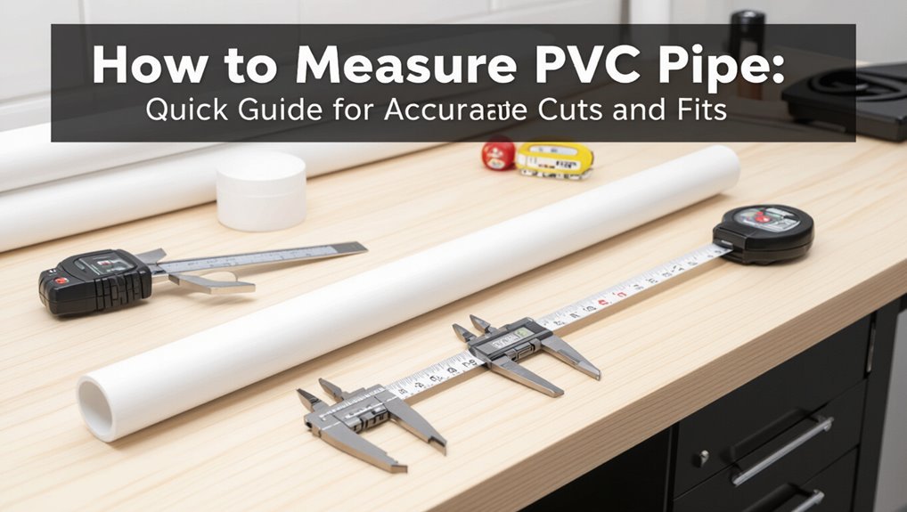
How to Measure PVC Pipe: Quick Guide for Accurate Cuts and Fits
Key Takeaway for Measuring PVC Pipe:
To accurately measure PVC pipe for cuts and fittings, follow these steps:
- Mark the Cut Point: Measure from the pipe end, accounting for socket insertion depth and saw kerf.
- Clamp for Stability: Secure the pipe to ensure a straight cut.
- Measure Outer Diameter: Use calipers or a tape measure across the widest point.
- Estimate Inner Diameter: Conduct fitting trials or use a string to measure circumference.
- Calculate Wall Thickness: Use the formula (OD−ID)/2 to determine the schedule.
- Dry-Fit Assembly: Verify the fit and make any necessary adjustments incrementally.
These steps will help ensure precise measurements and successful fittings for your PVC projects. For more detailed tips on tools, schedules, and common mistakes, continue reading.
Quick Method: Measure PVC Length for Straight Cuts
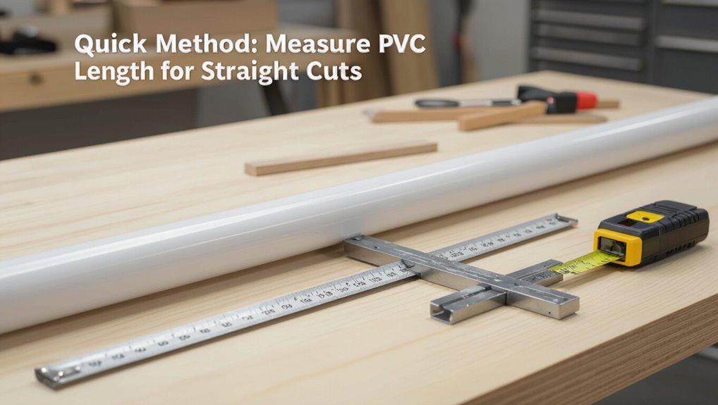
A simple, reliable way to measure PVC for straight cuts begins by marking both the cut location and any reference points on the pipe, then measuring from the end to the mark with a tape measure held flat against the pipe.
The installer notes whether measurements are to the end, to a socket, or accounting for fitting insertion depth. They transfer marks with a permanent marker or pencil, recheck distances, and clamp the pipe to prevent movement.
A square or combination square guarantees a perpendicular line. Cuts follow the marked line using a saw appropriate for PVC; burrs are removed and length rechecked before assembly.
Measure PVC Outer Diameter (OD) Quickly
To measure a PVC pipe’s outer diameter quickly, one should measure straight across the widest point of the round section.
A caliper gives the most precise reading, while a tape measure or ruler can suffice for rougher measurements.
Record the measurement to the nearest millimeter or sixteenth inch for accuracy.
Measure Across Widest Point
Several quick checks identify the pipe’s outer diameter (OD) by measuring straight across the widest external points of the round section.
The inspector positions a ruler or measuring device perpendicular to the pipe axis, ensuring it contacts opposing outer edges. Visual alignment prevents diagonal readings that overstate the OD.
For slightly oval or deformed pipes, take multiple measurements at different rotational positions and record the largest value as the effective OD.
Note any fittings, chamfers or burrs and measure beyond them on the true cylindrical surface. Document the result, rounded to the nearest practical unit for cutting and fitting decisions.
Use Calipers Or Tape
Measuring across the widest point establishes a baseline, after which calipers or a tape measure provide a faster, more precise way to capture the PVC outer diameter (OD).
The technician selects digital calipers for accuracy to 0.01 mm when available; analog calipers or a flexible tape serve when conditions or budget dictate.
For calipers, align jaws perpendicular to the pipe axis, close gently until contact, and read the display or scale.
For tape, wrap snugly around the circumference, note the measurement, and divide by π for OD.
Record results and repeat at several points to confirm roundness before cutting or joining.
Measure PVC Inner Diameter (ID) Without Tools
When no calipers or rulers are available, a quick, reliable estimate of a PVC pipe’s inner diameter can be made using common items and simple comparison techniques; this method relies on matching the pipe opening to objects of known size (coins, bolts, or other pipes) and using basic geometry if partial fits are observed.
The observer notes which items slip inside, which jam, and whether an item sits flush. Record sizes, then interpolate between the largest fitting and smallest nonfitting object. For partial fits, measure the visible chord and apply simple circle geometry or use string circumference to estimate diameter.
- Compare coins or bolts.
- Try smaller pipes.
- Use string to measure circumference.
- Interpolate between fits.
Measure PVC Wall Thickness and Identify Schedule
To determine a PVC pipe’s wall thickness and thereby identify its schedule, the user should measure the outside diameter (OD) and the inner diameter (ID) and calculate thickness as (OD − ID)/2; wall thickness is the defining characteristic of schedules (e.g., Schedule 40, Schedule 80), so comparing the measured thickness to manufacturer tables or standardized schedule charts will reveal the pipe’s classification. Measure with calipers at several points, average results, and note markings on the pipe for confirmation. If ambiguous, consult manufacturer specs or a plumbing chart for pressure ratings and schedule equivalence.
| Measurement | Note |
|---|---|
| OD | Measure across outside |
| ID | Measure inside bore |
| Thickness | (OD−ID)/2 |
| Repeat | Average multiple spots |
| Verify | Use manufacturer chart |
Nominal Pipe Size vs Actual Dimensions: Quick Guide
Nominal pipe size refers to a labeled designation that does not always match the pipe’s actual measurements.
The difference between outer diameter (OD) and inner diameter (ID) depends on wall thickness (schedule) and is critical when fitting or calculating flow.
A simple conversion chart helps translate nominal sizes into their corresponding OD and ID values for quick reference.
Nominal Size Meaning
Although the term sounds like the pipe’s measured diameter, “nominal size” is a label that represents a rough, standardized designation rather than an exact physical dimension.
The phrase simplifies ordering and compatibility across fittings, schedules, and systems, while actual measurements can differ by wall thickness and manufacturing tolerances. It guides selection without substituting for precise measurement when cutting or connecting.
Users should confirm compatibility by checking manufacturer specs and using calipers or tape for critical fits. Common confusion arises when nominal size matches neither internal nor external dimensions directly, making verification essential for reliable assemblies.
- Standardized identifier for selection
- Not an exact measurement
- Depends on schedule and material
- Verify with manufacturer specs
Outer And Inner Diameters
After explaining what a nominal size represents, it helps to contrast that label with the pipe’s actual outer and inner diameters.
The outer diameter (OD) is the measured width across the pipe’s exterior and is fixed for a given nominal size and schedule, ensuring fittings mate properly.
The inner diameter (ID) varies with wall thickness; thicker walls reduce ID and affect flow capacity.
When measuring, use calipers for OD and measure wall thickness or enter ID directly if accessible.
Understanding OD versus ID prevents mismatched fittings, incorrect flow calculations, and cutting errors during installation.
Measurement Conversion Chart
A compact conversion chart maps common nominal pipe sizes to their actual outer and inner diameters and typical wall thicknesses, providing a quick reference for selecting fittings, calculating flow, and planning cuts.
The chart clarifies that nominal size is a label, not a literal measurement, and highlights variations across schedules (e.g., Schedule 40 vs Schedule 80). Users rely on it to verify coupling compatibility, compute clear bore, and estimate material removal for joints.
Reference tables should list units, tolerances, and standard fittings to prevent mistakes.
- Nominal vs actual dimensions
- Outer diameter values
- Inner diameter and wall thickness
- Schedule and tolerance notes
Convert Nominal Size to OD and ID (Reference Table)
Converting PVC nominal sizes to actual outside and inside diameters requires a quick reference table because nominal sizes do not equal measured dimensions. A concise table helps identify OD and ID for common nominal sizes, aiding selection and fittings. The following shows nominal size versus typical OD/ID ranges; specific pipe type and schedule alter exact ID.
| Nominal Size | Typical OD / ID (in) |
|---|---|
| 1/2″ | 0.840 OD / 0.622 ID |
| 3/4″ | 1.050 OD / 0.824 ID |
| 1″ | 1.315 OD / 1.029 ID |
| 2″ | 2.375 OD / 2.067 ID |
Users should verify with manufacturer data for precise work.
Use a Tape Measure for Precise PVC Cuts
The installer measures twice before cutting to confirm the desired length.
They hold the tape measure steady and square to the pipe to avoid parallax errors.
A clear mark is made at the measured point to guarantee a precise cut.
Measure Twice, Mark Once
Measure twice, mark once must guide every PVC cut to prevent wasted material and misaligned joints. The craftsman confirms measurements, accounts for fitting depth and saw kerf, then repeats the check before marking.
Consistent procedure reduces errors and saves time on rework. Visual alignment and numeric verification together guarantee repeatable accuracy across multiple pieces.
- Verify overall length and subtract fitting insertion depth.
- Add saw kerf allowance to cut marks.
- Re-measure the marked points from both ends.
- Inspect marks for straightness and consistent placement before cutting.
Hold Tape Steady
Clamp the tape measure firmly against the pipe so it cannot slip while the mark is being set. The installer holds the tape taut, aligns the zero with the cut start, and reads the measurement at eye level to avoid parallax error.
A fingertip or spring clamp secures the blade; a small piece of tape can lock the position for solo work. For long runs, support the pipe to prevent sagging which alters length.
Recheck the mark before cutting; then re-measure between fittings if needed. Consistent technique produces repeatable, accurate cuts and guarantees proper fit without waste.
Mark Cut Lines for Square, Clean PVC Ends
Mark a clear, thin cutting line around the pipe at each measured point using a fine-tip marker or a wraparound pencil guide to guarantee the line is perfectly perpendicular to the pipe’s axis.
The writer notes that consistent, visible lines reduce parallax errors during sawing and sanding. Lightly score scored PVC for brittle grades; avoid deep gouges that distort fit.
Rotate the pipe and inspect the mark from multiple angles to confirm alignment with fittings. Clean the surface before marking to remove debris or moisture that can smear ink and obscure the line.
- Use fine-tip marker
- Employ wraparound guide
- Inspect alignment
- Clean before marking
Measure and Cut Mitered or Angled PVC Joints
After ensuring square, clean end faces, the craftsman prepares for angled joints by determining the exact cut angle and the joint geometry required—bevels, mitered ends, or compound cuts for offset runs.
Measurements account for wall thickness and insertion depth where applicable; a protractor or digital angle finder transfers the angle to the pipe.
Clamp the pipe securely in a miter box or jig, mark both cut points for paired pieces, and cut with a fine-tooth saw or PVC scoring tool to limit tear-out.
Deburr and light-sand cut faces, verify fit dry, and adjust incrementally until mating faces seat flush without gaps.
Measure for Socket Fittings and Slip Joints
Measure the insertion depth and socket orientation before cutting so each mating piece seats fully without stressing the joint. The technician notes socket depth, marks insertion line on the pipe, and accounts for wall thickness and primer/solvent thickness.
For slip joints, allowance for movement and washer clearance is checked; for push-fit sockets, guarantee pipe end is deburred and square.
- Record socket depth with a probe or sample insertion.
- Mark cut line at measured insertion point plus chamfer allowance.
- Verify alignment so sockets sit flush without over-insertion.
- Re-check after dry-assembly for interference or misalignment.
Measure for Threaded PVC Connections
When switching from socket or slip fittings to threaded connections, the technician shifts focus from insertion depth to thread engagement and overall length so mating threads fully engage without bottoming out or leaving gaps. They measure exposed thread length on both male and female parts, account for thread pitch, and include any sealant or tape thickness. Mark cutting points so the assembled length meets run requirements. Verify thread compatibility (NPT vs BSP) before final cuts. Test-fit threads by hand before sealing to confirm engagement and alignment. Record final cut measurements for repeatability on similar runs.
| Item | Check |
|---|---|
| Thread type | Match pitch |
| Length allowance | Include sealant |
Measuring Pipe Length With Couplings and Adapters
Because couplings and adapters change the effective run length, the technician must include their insertion depths, shoulder positions, and any gasket or ferrule thickness when marking and cutting PVC pipe.
The practitioner records each fitting’s contribution, subtracts or adds to the measured run, and verifies clearance at joints before final cuts. Attention to tolerances prevents tight assemblies or gaps.
For quick reference, a checklist guides consistent measurement and marking.
- Identify fitting types and measure their physical length.
- Note shoulder or stop positions on each fitting.
- Include gasket/ferrule thickness in totals.
- Adjust cut marks for cumulative fit offsets.
Measure Insertion Depth for Push-Fit Fittings
A technician determines the correct insertion depth for push-fit fittings by locating the internal stopping point and measuring from the pipe end to that stop; this dimension guarantees a secure, leak-free engagement.
The technician marks the pipe at the measured depth, confirming the mark is visible after insertion. Measurements account for pipe deburring and squaring; rough or angled ends can prevent full engagement.
For adapters with built-in seals, the same stop location is used. A test push confirms seating against the stop.
Final inspection verifies the mark aligns with the fitting shoulder and that no gap or misalignment remains.
Allowances for Solvent-Weld Depth and Glue Gap
The section outlines how solvent-weld socket depth is measured and why it matters for joint strength.
It also explains the allowance for a small glue gap to guarantee proper adhesive distribution without compromising fit.
Measurements and clearances provided here guide accurate cutting and marking for reliable solvent-weld connections.
Solvent-Weld Socket Depth
Several millimeters of allowance are typically left when measuring socket depth to accommodate solvent-weld penetration and a small glue gap; this guarantees the pipe bottoms out without preventing full solvent contact in the joint.
The socket depth must match manufacturer specifications and consider pipe insertion length, wall thickness, and fitting tolerances. Accurate marking and a depth-stop ascertain consistent joints. Over-insertion risks solvent starvation; under-insertion weakens engagement.
- Confirm nominal socket depth from fitting datasheet.
- Measure pipe insertion length including chamfer and debris allowance.
- Mark depth with a square, visible line.
- Use a stop or jig for repeatable assemblies.
Allowance For Glue Gap
Proper solvent-weld joints require a small, controlled glue gap between pipe and fitting to ascertain full solvent penetration and chemical fusion without creating voids or stress concentrations. A measured allowance compensates for manufacturing tolerances and guarantees adequate adhesive film thickness. The installer should follow manufacturer depth charts and apply consistent seating to maintain the gap — typically 0.005–0.020 inches for common schedules. Excessive gap weakens the joint; zero gap prevents solvent flow. Clean, chamfered ends and light primer promote capillary action. Record dimensions and test assemblies when tolerances are critical to confirm bonding performance.
| Item | Typical Allowance |
|---|---|
| PVC Schedule 40 | 0.005–0.015 in |
| PVC Schedule 80 | 0.005–0.020 in |
| Large diameters | Increase slightly |
| Critical fittings | Verify with maker |
Account for Measurement Error and Cutting Kerf
When working with PVC, small inaccuracies in measuring and the material removed by a saw blade—the cutting kerf—combine to shorten final pieces, so it is essential to plan and adjust cuts accordingly. A disciplined approach reduces waste and guarantees fit.
- Measure twice, mark once: confirm lengths and mark cut lines with a fine pencil or scribe.
- Know the kerf: check the blade width and subtract that from the total length per cut.
- Factor cumulative error: for multiple segments, distribute small allowances so total equals required run.
- Test-fit and trim minimally, preserving planned dimensions while compensating for any residual error.
Measure Long PVC Runs With a Measuring Wheel
For long continuous runs, a measuring wheel speeds layout by recording distance while one person walks the line.
The operator should select a wheel calibrated for the terrain and pipe size, mark intervals or change points as they go, and note locations for fittings and offsets.
Recorded distances must then be adjusted to include fittings’ added lengths before cutting.
Choose The Right Wheel
Which measuring wheel best suits a long PVC run depends on surface, distance, and required accuracy.
Selection should prioritize wheel diameter for roll smoothness, tread for grip on gravel or turf, durable frame for jobsite wear, and an accurate counter calibrated to wheel circumference.
Consider portability versus stability when choosing collapsible or fixed models.
For extended distances, choose larger wheels to reduce error and operator fatigue; for rough terrain, opt for knurled or pneumatic treads.
Budget stainless steel or aluminum frames and simple resettable counters for reliability.
Match wheel specs to the project to guarantee consistent, repeatable measurements.
- Wheel diameter
- Tread type
- Frame material
- Counter accuracy
Mark Measurement Intervals
Begin by establishing clear, evenly spaced reference marks along the planned route so each measured segment can be quickly identified and recorded.
The technician walks the path with the measuring wheel, stopping at each interval to place high-contrast marks on adjacent surfaces or attach temporary flags.
Record cumulative readings at each mark to verify consistency and detect wheel slip or obstacles. For long runs, mark every few feet or meters depending on project tolerance and terrain.
Use weather-resistant markers or tape for outdoor work. Periodically recheck earlier marks against the wheel to guarantee no cumulative error before cutting or final installation.
Account For Fittings
When measuring long PVC runs with a measuring wheel, technicians must add allowance for each fitting so cut lengths and material lists reflect true installed dimensions. The measuring wheel captures linear distance but fittings add effective length; installers consequently translate fittings into equivalent straight-pipe lengths before finalizing measurements.
Accurate allowance prevents shortfalls and rework.
- Catalog fittings and note manufacturer effective lengths.
- Convert each fitting to its equivalent pipe length and sum totals.
- Add summed fitting allowance to wheel-measured run length.
- Round to practical cutting increments and verify against site clearances before ordering materials.
Measure PVC Inside Tight Spaces and Behind Fixtures
Measuring PVC inside tight spaces and behind fixtures requires compact tools and a steady method to guarantee accurate runs without dismantling surrounding components.
The technician uses a flexible tape, pocket ruler, or bending wire to follow pipe centerlines and record bend offsets. Markings should note distance to nearest access point and any concealed fittings.
When visibility is limited, a flashlight and small mirror clarify alignment. Allowances for wall thickness and fitting depth are added to the measured run. Measurements are double-checked from both ends when possible.
Clear labeling and concise notes prevent errors during cutting and installation.
Measure Flexible PVC and Thin-Wall Tubing
Flexible PVC and thin-wall tubing require slightly different measurement priorities than rigid pipe.
First, the outer diameter should be measured accurately, then the wall thickness verified to determine pressure rating and fittings compatibility.
A flexible tape or caliper is recommended to follow curves and record precise dimensions.
Measure Outer Diameter
How should one determine the outer diameter of flexible PVC or thin-wall tubing to guarantee proper fittings and clearances? The process requires accurate caliper measurement across the widest external span, repeating at multiple points to detect ovality. Measurements inform selection of slip or compression fittings and any required adapters.
Record values to the nearest 0.1 mm or 1/64 inch, noting manufacturing tolerances. Avoid relying on nominal pipe size labels alone; confirm actual dimensions before procurement or installation.
- Use a vernier or digital caliper perpendicular to axis.
- Measure at several axial positions.
- Average measurements if slight ovality exists.
- Compare against fitting specifications.
Check Wall Thickness
One critical step is determining the wall thickness of flexible PVC or thin-wall tubing to guarantee pressure ratings, fit with barbs or compression sleeves, and long-term durability.
Measure wall thickness with calipers at multiple points to account for variability; record the smallest reading. For very thin walls, use a depth micrometer or a sharp-edge caliper technique to avoid compressing the material.
Compare measurements to manufacturer specifications or applicable standards to confirm suitability for the designated pressure and connector type.
Note that wall thickness affects bend radius, collapse resistance, and chemical compatibility; document results before cutting or assembling fittings.
Use Flexible Tape
When measuring flexible PVC and thin-wall tubing, a flexible tape measure provides a quick, conforming way to capture outside circumference and length without distorting the material.
The tape’s pliability follows curves and soft walls, preventing compression that skews diameter readings. For circumference, wrap the tape snugly but not tight; record where the zero meets the tape.
For length, align the tape along the centerline, avoiding kinks. Note any fittings or flares and measure to their start.
Repeat measurements to confirm consistency and average if slight variation occurs.
- Wrap snugly, avoid compression
- Measure along centerline
- Account for fittings
- Repeat and average
Measure Multi-Piece Assemblies Before Final Cuts
Before cutting, the assembler should dry-fit the entire multi-piece assembly and measure across the joined sections to verify overall length and alignment.
They note cumulative tolerances from fittings, socket depths, and any offsets. Measurements should be taken along the centerline and along critical faces where the assembly meets other components.
Mark each pipe with its cut location, accounting for insert depths and planned joint gaps. Use a rigid straightedge to confirm straightness and detect angular misalignments.
Recheck lengths after tightening temporary connections. Record final measured cut lengths before disassembly to guarantee repeatable, accurate cuts.
Prep Steps and Re-Measure Checks Before Solvent-Welding
After confirming final cut lengths and alignment from the dry-fit, the assembler turns attention to the prep steps and re-measure checks that precede solvent-welding.
Surfaces are cleaned, burrs removed, and fit tolerances re-verified to prevent misalignment once adhesive is applied. A brief checklist confirms component identity and orientation. Final gap allowances and socket depths receive measurement, marking insertion lines where required.
- Inspect and de-burr cut ends; wipe with solvent to remove debris.
- Re-measure lengths and insertion depths against assembly drawings.
- Verify part orientation and matching reference marks.
- Confirm environmental conditions suitable for solvent welding.
Check Perpendicularity After Cutting PVC
After cutting, a quick visual alignment check confirms whether the pipe end appears square to its axis.
For precise verification, a carpenter’s square or combination square is placed against the cut end to reveal gaps or tilt.
Any detected out-of-square condition should be corrected by re-cutting or sanding before assembly.
Visual Alignment Check
When a PVC pipe has been cut, a quick visual alignment check confirms whether the end face is perpendicular to the pipe axis. The inspector holds the pipe at eye level, rotating it slowly to spot light gaps, uneven edges, or visible bevels.
Any deviation appears as an inconsistent shadow line or angled rim. Minor imperfections can be sanded; larger miscuts require recutting. Consistent technique reduces repeat errors.
- Rotate pipe while viewing along axis to reveal misalignment.
- Inspect for asymmetrical light leakage and uneven bevels.
- Note burrs or scallops indicating blade wandering.
- Decide: sand, recut, or reject.
Use A Square Tool
A square tool provides a precise, objective way to verify that a PVC pipe end is cut perpendicular to its axis: the inspector seats the square against the pipe face and checks for uniform contact around the circumference, using light gaps or a feeler to detect any tilt.
The method isolates perpendicularity from visual bias. A machinist’s square or combination square works best; larger diameters may require a straightedge and multiple contact points.
Rotate the pipe and recheck to identify high or low spots. If gaps appear, mark and re-cut or sand evenly until the square registers continuous contact, ensuring reliable joint alignment.
Use Calipers for Precise OD and ID Checks
Measure both the outer and inner diameters with calipers to get precise, repeatable readings: place the caliper jaws gently on the pipe’s outside for OD, then use the smaller inside jaws to capture the ID, ensuring the tool is perpendicular to the pipe axis and avoiding tilted or overcompressed contact.
The practitioner notes readings at multiple positions to detect ovality, records values, and compares them to nominal pipe sizes and fittings. Lightly clean contact surfaces and close the caliper slowly to avoid spring error.
Calipers provide finer resolution than tapes or rulers, improving fit decisions.
- Verify zero before measuring
- Take three measurements around circumference
- Average or note variation
- Record to appropriate precision
Use a Depth Gauge to Verify Socket Depths
A depth gauge is used to verify the socket depth of each fitting before assembly.
The gauge is inserted to the backstop and the measurement recorded, then the fitting is marked at the mating line.
After marking, the socket is rechecked with the gauge to confirm the final depth matches the required specification.
Confirm Socket Depth
Confirm socket depth by using a calibrated depth gauge to verify each fitting will seat fully and produce the desired glue joint.
The technician aligns the gauge with the socket axis, noting shoulder contact and recording depth. Consistent measurement prevents under- or over-insertion that compromises seal integrity.
Measurements are compared to fitting specifications; out-of-tolerance sockets are marked for repair or rejection. Repeat checks after chamfering or reaming to verify no change.
- Align gauge squarely with socket axis.
- Record depth where gauge shoulder meets socket rim.
- Compare reading to manufacturer tolerance.
- Mark or remediate sockets outside specification.
Measure With Gauge
Using a calibrated depth gauge, the technician verifies each socket depth by seating the gauge squarely in the fitting and noting where the shoulder contacts the rim. Readings are taken at multiple orientations to account for molding variance and recorded immediately.
Measurements are compared to manufacturer specifications and project tolerances; any deviation beyond allowable limits prompts inspection or replacement of the fitting. The gauge eliminates guesswork from visual checks and provides repeatable data for fittings of different sizes.
Proper technique includes holding the gauge perpendicular, avoiding debris between shoulder and rim, and confirming gauge calibration before and after a measuring session.
Mark And Recheck
Before final assembly, the technician marks the verified socket depth on each fitting and immediately rechecks with the depth gauge to affirm the mark aligns with the measured shoulder position.
The process minimizes assembly errors and confirms that insertion limits match mating parts. Verification prevents over-insertion, binding, or inadequate engagement that compromise seals. Marking is concise and permanent enough to remain visible through handling.
Rechecking after blind adjustments ensures initial measurements weren’t disturbed.
- Confirm gauge calibration before use.
- Insert pipe to shoulder and scribe mark.
- Re-measure mark against gauge depth.
- Record final depth for quality control.
Label Measured Pipes for Installation Order
Once all pipes are cut to length and dry-fit, label each piece clearly with its installation sequence so assembly proceeds smoothly on-site.
Use a waterproof marker to note numbers, orientation, and connection points directly on the pipe or on removable tape. Include brief notes for fittings, glue or primer application, and any special angles.
Group labeled pieces in order of installation on a clean surface or in bins to prevent mix-ups. Keep a simple map or list showing label-to-location correspondence for reference.
Clear, consistent labeling reduces assembly time, prevents errors, and aids any teammate joining the job.
Measuring PVC for DWV (Drain/Waste/Vent) Systems
After labeling and organizing cut pieces for the fixture run, attention shifts to measuring PVC for DWV systems, where slope and access take precedence.
Measurements prioritize continuous gravity flow: calculate run length, include fitting offsets, and set minimum slope (typically 1/4″ per foot for horizontal drains).
Account for cleanout locations and future access when positioning fittings. Confirm trap arm lengths and vent placement to code.
Use a rigid tape and mark reference points; dry-fit components before final cutting to verify alignment.
- Calculate effective run including fittings
- Apply required slope per code
- Locate cleanouts and vents
- Dry-fit, then cut
Measuring PVC for Pressurized Water Systems
Several key measurements determine success when laying out PVC for pressurized water systems: total run length, fitting offsets, valve locations, and allowances for thermal expansion.
Measure from centerline to centerline for elbows and tees to account for effective flow path. Include coupler and fitting lengths when calculating cuts. Mark isolation valves and service points for accessibility and pressure testing.
Factor in slope only where code requires for combined systems; otherwise maintain level runs to prevent air pockets. Allow a small expansion gap at fixed supports and calculate hanger spacing per pipe size and working pressure to prevent sagging or stress.
Measure Electrical Conduit vs Plumbing PVC Differences
Many measurements used for plumbing PVC also apply to electrical conduit, but key differences in purpose, code requirements, and fitting conventions change what must be measured and how.
Electrical conduit (PVC Schedule 40/80 or EMT equivalents) prioritizes internal diameter for wire fill, run length for conduit bends, and clearance for junction boxes.
Plumbing PVC focuses on flow capacity, pressure ratings, and solvent-welded solvent allowances.
Measurement methods differ: conduit often uses trade size and conduit body spacing; plumbing uses nominal pipe size and hub-to-hub dimensions.
Accurate documentation guarantees code compliance and proper fitment across disciplines.
- Internal diameter vs nominal size
- Trade size conventions
- Fitting depth and socket allowances
- Code-specific spacing and fill
How Temperature and Thermal Expansion Affect Measurements
Temperature changes cause PVC pipe to expand and contract, and that dimensional movement must be accounted for when taking and recording measurements.
PVC’s coefficient of thermal expansion means length changes several thousandths of an inch per foot for each degree Fahrenheit. Measure pipes at expected in-service temperature or apply correction factors for extremes.
Record ambient temperature with each measurement and note whether fittings allow movement. For buried or sun-exposed runs, include expansion joints or additional clearance in cut lengths.
Consistent measurement practice minimizes gaps, buckling, and stress on joints caused by unanticipated thermal movement.
Choosing the Right Tools for Accurate PVC Measurement
A clean tape measure, a caliper, and a square form the core toolkit for accurate PVC measurement; selecting instruments with the right precision and durability assures cuts and fittings align as planned.
Reliable tools reduce rework and guarantee consistent results across projects. Lightweight, rust-resistant tape measures with clear markings suit long runs.
Vernier or digital calipers verify wall thickness and OD for snug fittings. A carpenter’s square or combination square confirms square cuts and perpendicular joints.
A marker and depth stop add repeatability. Quality blades on cutting tools preserve measured lengths by minimizing deformation during the cut.
- Tape measure
- Caliper
- Square
- Marker/depth stop
Common Measuring Mistakes and How to Avoid Them
Overlooking small measurement errors often leads to wasted material and misfit joints; recognizing common pitfalls—misreading tape markings, failing to account for wall thickness, and cutting with a dull blade—prevents those setbacks.
Practitioners should avoid measuring from the wrong pipe end, ignoring fitting insertion depth, and relying on stretched or kinked tape. Environmental factors like temperature-induced expansion deserve consideration when tolerances are tight.
Using blunt tools or unstable work supports causes uneven cuts and inaccurate lengths. Markings should be double-checked against a calibrated square or gauge.
Consistent technique, proper tools, and clear notation minimize rework and improve fit reliability.
Double-Check Measurements With a Dry-Fit Mockup
Before committing to solvent or primer, the installer should assemble a dry-fit mockup of the cut pipes and fittings to confirm lengths, alignment, and insertion depths. This practice verifies fit, reveals interference, and allows quick adjustments without waste.
The mockup helps confirm orientation of threaded pieces, spacing for supports, and final clearances. Marking reference points during the dry fit preserves measurement intent when disassembled for final assembly.
- Check insertion depth against fitting shoulder.
- Verify overall run length with couplings in place.
- Confirm alignment with adjoining fixtures and brackets.
- Note required trimming or reaming before gluing.
Measuring Checklist for Repetitive PVC Jobs
For repetitive PVC jobs, a concise measuring checklist guarantees consistency, reduces waste, and speeds installation by standardizing steps and reference points.
The checklist lists project profile, pipe diameters, required lengths, and joinery types. Include measurement method (inside or end-to-end), allowance for fittings, and glue or solvent depth.
Specify tool calibration, mark color coding, and batch labeling. Record stumble points like offsets or slope.
Assign verification stages: initial cut, dry-fit, final trim. Log measurements and deviations for process improvement.
Maintain one printed checklist at the workbench and one digital version for quick updates and team access.
Conclusion
Like a compass guiding a ship, precise measurement steers every PVC project away from costly detours. The reader now understands how to gauge length, OD, ID, wall thickness and schedule, choose proper tools, avoid common mistakes, and verify fits with dry-fit mockups. Armed with the checklist, repetitive jobs become predictable and swift. With care and consistent measurement, each cut and joint will align, saving time, material, and frustration.