
How to Seal Hydraulic Fittings: A Step-by-Step Guide to Leak-Proof Connections
To effectively seal hydraulic fittings and ensure leak-proof connections, start with clean, undamaged surfaces and select the appropriate seal type—be it threads, flares, O-ring bosses, or compression joints. Inspect and clean all components, apply PTFE tape or a compatible sealant to male threads, check and lubricate O-rings, and adhere to manufacturer torque specifications. After assembly, conduct staged pressurization and leak tests, documenting your results and following scheduled maintenance intervals. For in-depth procedures and product recommendations, refer to the subsequent sections.
How to Achieve Leak-Proof Hydraulic Fittings: Quick Overview
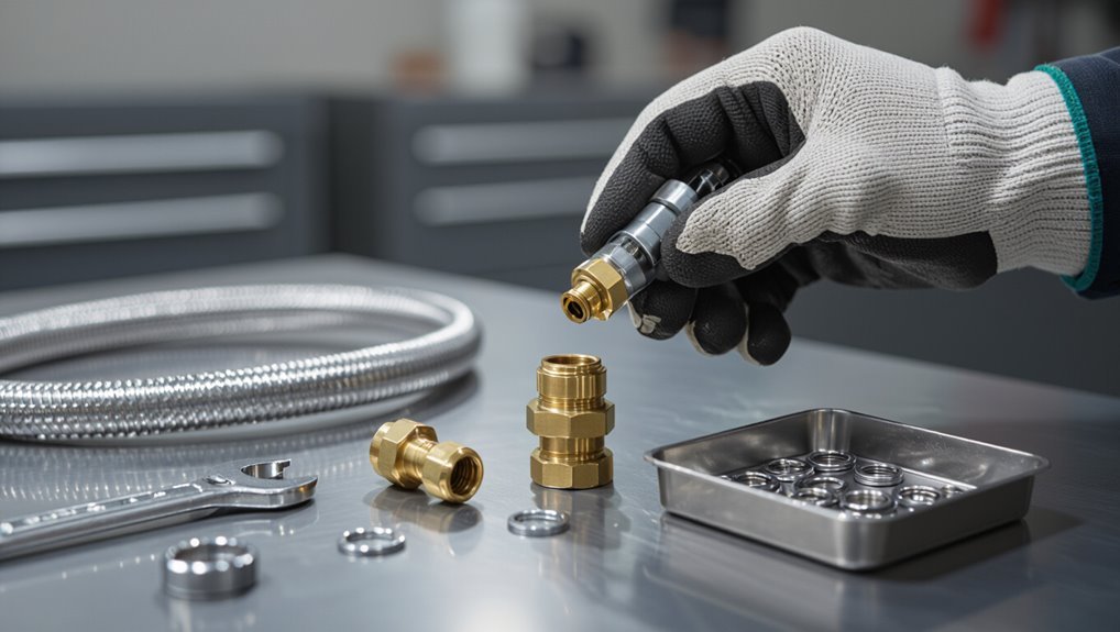
A properly sealed hydraulic fitting shows no visible fluid, maintains correct alignment, and retains its original sealing surface without deformation.
Signs that a fitting needs resealing or replacement include persistent weeps, corrosion, cracked seals, or repeated torque loss.
Prompt action on these indicators prevents system contamination and pressure loss.
What a Properly Sealed Hydraulic Fitting Looks Like
Several clear indicators distinguish a properly sealed hydraulic fitting from one that will leak: uniform contact around the mating surfaces, absence of visible gaps or sealant squeeze-out in threaded joints, and no seepage after pressurization.
Visual inspection shows clean, undamaged surfaces and correct torque. Functional verification under working pressure confirms integrity.
Proper assembly, correct components, and routine checks reflect how to seal hydraulic fittings reliably.
When to Re-seal or Replace Fittings
When should a hydraulic fitting be re-sealed or replaced depends on visible damage, performance under pressure, and maintenance history.
Inspect for corrosion, cracks, stripped threads, or persistent seepage after tightening.
Re-seal only for minor surface leaks with appropriate sealant; replace fittings showing structural damage, recurring leaks, or compromised torque retention.
Prioritize replacements on critical systems and follow manufacturer intervals.
Essential Concepts of Hydraulic Sealing
A clear understanding of fitting types and connection methods—threaded, flared, compression, and quick-connect—is fundamental to selecting the right sealing approach.
Common seals such as O-rings, PTFE tape, liquid thread sealants, and metal-to-metal interfaces each have specific advantages and limitations.
Pressure, temperature, and fluid compatibility dictate material choice and installation practice to guarantee reliable, long-lasting seals.
Types of Hydraulic Fittings and Connection Methods
Many hydraulic systems rely on a limited set of fitting types and connection methods—threaded, flared, compression, O-ring face seal (ORFS), and quick-connects—that determine sealing approach, assembly technique, and leak risk.
Each style presents distinct mating geometry, torque requirements, and inspection needs.
Choice depends on pressure, fluid type, vibration, serviceability, and compatibility; proper selection reduces failure modes and simplifies maintenance.
Common Seal Types (O-rings, PTFE tape, thread sealants, metal-to-metal)
Several common seal types—elastomer O-rings, PTFE tape, anaerobic and paste thread sealants, and metal-to-metal seats—offer distinct sealing mechanisms, limitations, and application requirements in hydraulic systems.
O-rings provide elastic compression seals; PTFE tape fills thread gaps. Thread sealants cure or remain pliable to prevent leaks. Metal-to-metal seats rely on precision machining and correct torque for deformable or rigid contact sealing.
How Pressure, Temperature, and Fluid Compatibility Affect Seals
Hydraulic seal performance depends critically on three interacting factors: pressure, temperature, and fluid compatibility.
Pressure influences extrusion risk and required hardness; temperature alters elastomer flexibility, swelling, and ageing; fluid chemistry affects swelling, degradation, and seal swelling or shrinkage.
Correct material selection, pressure-rated designs, and testing under expected thermal and chemical conditions guarantee reliable, long-term sealing in hydraulic systems.
Tools and Materials You Need
A clear inventory of inspection and preparation tools—cleaners, appropriate wrenches, and pressure/flow gauges—ensures fittings are assessed and prepared correctly.
A concise guide to sealing materials helps match thread sealants, PTFE tape, and flange gaskets to application pressures and fluids.
Required safety equipment and established best practices protect personnel and preserve seal integrity during installation.
Inspection and Preparation Tools (cleaners, wrenches, gauges)
Before any sealing work begins, proper inspection and preparation tools must be gathered to guarantee fittings are cleaned, measured, and adjusted correctly.
Essential items include lint-free cleaning cloths, solvent brushes, and compressed-air cans for debris removal; adjustable and torque wrenches for correct tightening; thread gauges and calipers for dimension verification; and inspection mirrors and flashlights to detect damage or contamination prior to sealing.
Sealing Materials Selection Guide
When selecting sealing materials for fittings, the technician should prioritize compatibility with system fluid, temperature range, pressure rating, and thread type to guarantee a reliable seal.
Choices include PTFE tape, anaerobic thread sealants, pipe dope, and O-ring compounds.
Match material chemical resistance and hardness to application, confirm cure times and service limits, and test assemblies under pressure.
- PTFE tape
- Anaerobic sealant
- Pipe dope
- O-rings
Safety Equipment and Best Practices
Although hydraulic fittings are small components, proper personal protective equipment and the right tools are essential to prevent injury and guarantee a leak-free assembly.
Wear safety glasses, gloves resistant to hydraulic fluid, and hearing protection when using power tools.
Use calibrated torque wrenches, flare and compression tool kits, thread sealant applicators, and clean lint-free rags.
Inspect tools and replace damaged items before each job.
Step-by-Step Process to Seal Threaded Hydraulic Fittings
A clear step-by-step procedure begins with inspecting threads and all mating components for damage or contamination.
Surfaces are then cleaned and prepared before applying PTFE tape or a compatible liquid thread sealant and allowing proper cure time.
The final stage is controlled torqueing with correct alignment to guarantee a leak-free connection.
Inspecting Threads and Components
Before any sealing compound or tape is applied, a careful visual and tactile inspection of all threads and mating components is essential to guarantee a reliable hydraulic connection.
The inspector checks for burrs, cross-threading, corrosion, wear, and damaged sealing surfaces.
Thread pitch and fit are verified with gauges or matching parts.
Any defect mandates repair or replacement before proceeding to sealing.
Cleaning and Preparing Surfaces
Begin by removing all visible contaminants—oil, grease, dirt, and old sealant—from both male and female threads using an appropriate solvent and a clean, lint-free cloth; verify solvents used are compatible with hydraulic fluids and materials.
Next, dry surfaces completely, inspect for burrs or corrosion, and lightly de-burr or polish damaged areas.
Finally, blow out threads with dry, oil-free compressed air before assembly.
Applying PTFE Tape Correctly
With clean, dry threads confirmed, the correct application of PTFE tape provides a reliable seal for threaded hydraulic fittings.
Wrap tape clockwise around male threads, overlapping each pass by about half the tape width. Apply two to three full turns for standard fittings, and avoid covering the first thread to prevent contamination.
Press tape into crevices, and trim excess before assembly.
Using Liquid Thread Sealants and Curing Times
When using liquid thread sealants on hydraulic fittings, technicians should select a product rated for hydraulic systems and follow a measured application and curing sequence to guarantee a reliable, pressure-safe seal.
Apply sparingly to male threads, avoiding core flow paths. Assemble per manufacturer wet or dry assembly instructions, observe recommended cure time at ambient temperature, and verify cure before pressurizing to prevent joint failure.
Proper Torqueing and Alignment
Proper torqueing and precise alignment are critical to creating leak-free connections and preventing thread damage or premature sealant failure.
Technicians should hand-start threads, guarantee mating faces are square, and use calibrated torque wrenches set to manufacturer specifications.
Apply torque in stages, recheck alignment, and avoid over-tightening.
Record final torque and fitting orientation for maintenance and traceability.
Leak-Testing After Assembly
Begin leak-testing immediately after assembly to verify sealing integrity and detect any joints that require adjustment.
The system should be pressurized slowly to operating pressure while inspecting fittings for seepage, bubbles, or pressure loss.
Use approved leak-detection fluid or electronic detectors, monitor gauges, and hold pressure for the recommended dwell time.
Document results, tighten or reassemble as needed, then retest until leak-free.
Step-by-Step Process to Seal Flare, O-Ring Boss, and Compression Fittings
The section explains how to inspect and replace O-rings and seals, including proper lubrication and installation techniques to prevent damage.
It then outlines assembly methods for flare and compression joints and the torque or seating procedures specific to non-threaded fittings.
Finally, it covers pressure testing and necessary adjustments to verify leak-free performance.
Inspecting and Replacing O-Rings and Seals
Inspecting and replacing O-rings and seals is essential to restoring leak-free connections in flare, O-ring boss, and compression fittings. Technicians should first depressurize the system, clean the area, and visually examine seals for cuts, nicks, flattening, or hardening.
Remove damaged seals, note size and material, match replacements, inspect mating surfaces for burrs or corrosion, and verify proper seating before reassembly and pressure testing.
Lubrication and Installation of O-Rings
Carefully lubricating and correctly installing O-rings is critical to creating reliable seals in flare, O-ring boss, and compression fittings. Technicians should select a compatible lubricant, apply it sparingly to avoid migration, and position the O-ring so it sits evenly without twists or pinches before reassembly.
Confirm groove cleanliness, inspect for damage, lightly coat mating surfaces, seat the O-ring uniformly, and verify compression limits to prevent extrusion and leaks.
Assembling Flare and Compression Joints
Having lubricated and seated O-rings properly, technicians proceed to assemble flare, O-ring boss, and compression joints using a methodical, torque-controlled sequence.
They align mating surfaces, verify flare angles and ferrule positions, hand-start threads to prevent cross-threading, and tighten in staged increments.
Inspectors confirm alignment, ferrule compression, and O-ring integrity visually before system pressurization and leak testing.
Torque and Seating Procedures for Non-threaded Fittings
Begin the sealing sequence by positioning the flare, O-ring boss, or compression fitting in its mating component, ensuring all contact surfaces are clean and the O-ring or ferrule is correctly seated.
Then apply specified assembly lubricant sparingly to the O-ring or sealing faces only. Hand-tighten to align components, then use a calibrated torque tool following manufacturer torque and rotation specifications.
Verify proper seating by measured torque and visual alignment.
Pressure Testing and Adjustments
Once fittings are torque-verified and visually seated, proceed to controlled pressure testing and any required adjustments to confirm a leak-free seal.
Gradually apply system pressure to working level, inspect flare, O-ring boss, and compression joints for seepage.
If leaks appear, relieve pressure, tighten incrementally per spec, replace damaged seals, retest.
Document results and restore normal operation only after sustained no-leak confirmation.
Sealing Reusable vs. Permanent Connections
The choice between reusable seals and permanent sealants hinges on service conditions and maintenance access: reusable seals suit connections that require periodic disassembly and inspection, while permanent sealants or replaced components are appropriate for long-term, high-pressure or inaccessible joints.
Guidance should cover proper maintenance of reusable seals, including inspection criteria, cleaning, and replacement intervals to preserve integrity.
It should also specify when a permanent solution or component replacement is safer or more cost-effective than repeated resealing.
When to Use Reusable Seals and How to Maintain Them
When components require periodic disassembly for inspection or replacement, reusable seals offer a practical balance between reliability and serviceability; they are selected for fittings that see routine maintenance, moderate pressures, and environments where contamination or wear is anticipated.
Reusable seals should be inspected, cleaned, lightly lubricated with compatible hydraulic fluid, and replaced if nicked or hardened. Proper seating and torque guarantee repeatable performance.
When to Use Permanent Sealants or Replace Components
Why choose a permanent seal or a replacement component over a reusable connection?
Permanent sealants suit damaged threads, mismatched materials, high-vibration or inaccessible joints where future disassembly is unlikely.
Replace components when wear, corrosion, or repeated failures compromise integrity.
Prioritize safety and long-term reliability: permanent methods and new parts reduce leak risk but sacrifice serviceability, so document choices for maintenance planning.
Diagnosing and Fixing Common Hydraulic Leaks
The text outlines methods to identify leak sources based on their location and symptoms, guiding the reader to distinguish between threaded, O-ring, and hose-end failures.
It then summarizes repair steps for each failure type, noting common causes and required replacement or resealing actions.
Finally, it compares temporary field repairs with full shop repairs, highlighting when a stopgap is acceptable and when proper bench work is necessary.
Identifying Leak Sources by Location and Symptom
Because leaks present differently depending on where they originate and how the system is operated, accurate diagnosis begins with correlating location and symptom.
Technicians inspect joints, hoses, ports and seals, noting spray, seepage, pressure loss or contamination to pinpoint sources before repair.
- Spray vs. seep indicates pressure and fitting type
- Wet spots trace along hose paths
- Reservoir contamination hints internal failure
- Intermittent drips suggest thermal or pressure cycling
Repair Steps for Threaded Leak, O-Ring Leak, and Hose End Failures
Begin by isolating the affected circuit and relieving system pressure before any disassembly to guarantee safety and accurate assessment.
For threaded leaks, remove, inspect threads, clean, apply correct sealant or replace damaged fittings, torque to spec.
For O-ring leaks, replace O-rings with proper material and lubricate.
For hose-end failures, cut back to sound hose or replace assembly, seat ferrules correctly and test under low pressure.
Temporary Field Repairs vs. Shop Repairs
Distinguish quickly between temporary field repairs and full shop repairs by evaluating leak severity, accessibility, available tools, and operational urgency:
Temporary fixes stabilize leaks—use clamps, patch sleeves, or thread sealants to restore function until scheduled downtime.
Shop repairs replace fittings, hoses, and seals, perform pressure testing, and inspect system contamination.
Choose shop work for recurrent, high-pressure, or safety-critical failures; use field repairs only as controlled short-term measures.
Materials Compatibility and Chemical Resistance
Selection of seal materials must be guided by the hydraulic fluid in use, since compatibility with oils, water-glycol, or synthetic fluids prevents swelling, hardening, or rapid degradation.
Equally important are the temperature and pressure limits of common elastomers (e.g., NBR, FKM, EPDM) because exceeding those ratings causes seal failure.
The following section compares typical seal compounds against fluid types and operating ranges to inform appropriate choices.
Matching Seal Materials to Hydraulic Fluids
Match seal materials to the specific hydraulic fluid in use to prevent swelling, hardening, cracking, or accelerated wear that leads to leaks and failure. Selection must consider fluid chemistry, additives, and contamination; compatibility charts guide choices like NBR, FKM, PTFE, or polyurethane to guarantee longevity and safety.
| Fluid Type | Seal Options | Emotional Cue |
|---|---|---|
| Mineral oil | NBR, PTFE | Relief |
| Synthetic ester | FKM, PTFE | Confidence |
| Phosphate ester | PTFE, FFKM | Trust |
| Water‑glycol | EPDM, PTFE | Security |
Temperature and Pressure Limits for Common Seal Materials
Several common seal materials used in hydraulic systems have well-defined temperature and pressure limits that dictate their suitability for specific applications.
Nitrile (Buna-N): −40°C to 120°C, moderate pressures;
Viton (FKM): −20°C to 200°C, high pressures and chemical resistance;
EPDM: −50°C to 150°C, low compatibility with petroleum oils;
PTFE: −200°C to 260°C, excellent pressure tolerance and chemical inertness.
Select by service conditions.
Preventive Maintenance and Inspection Schedule
A clear preventive maintenance and inspection schedule guides routine checks of fittings, torque, seal condition, and system pressure.
Inspectors should recognize common signs of seal wear—hardening, cracking, extrusion, or persistent seepage—and establish criteria for replacement.
Accurate record-keeping of inspections, repairs, and leak history enables trend analysis and timely interventions.
Routine Inspection Checklist
Routine inspections should follow a concise checklist that prioritizes fluid condition, hose and fitting integrity, connection torque, and evidence of leaks or abrasion.
Inspection records should note date, inspector, component ID, and any corrective actions. Frequency should match operating hours and environment. Immediate containment for observed leaks is required.
- Verify fluid clarity and contamination levels
- Inspect hose covers and fittings for damage
- Check torque against specifications
- Document and tag defects for repair
Signs of Seal Wear and When to Replace
Many hydraulic seal failures begin with subtle changes that, when tracked, predict imminent loss of function.
Technicians should watch for hardening, cracking, extrusion, swelling, surface pitting, or uneven wear. Increased leakage, pressure fluctuations, or contamination ingress signal replacement.
Replace seals showing dimensional loss, brittle texture, or compromised lips. Adhere to OEM intervals and replace immediately if performance or safety is affected.
Record-Keeping and Tracking Leak History
Following signs of seal deterioration, systematic record-keeping and leak-history tracking provide objective data to guide replacement timing and preventive actions.
A standardized log should capture date, location, severity, repair type, parts used, and technician.
Trend analysis identifies recurrent failure points, informs gasket selection, and adjusts inspection intervals.
Digital records enable alerts, spare-parts forecasting, warranty claims, and continuous improvement of sealing procedures.
Common Mistakes and How to Avoid Them
Common seal-related errors include over‑tightening or under‑tightening connections, using the wrong sealant or tape, and failing to prepare threads or mating surfaces properly.
Each mistake increases the risk of leaks, component damage, or contamination.
Clear torque procedures, correct sealant selection, and proper cleaning and inspection prevent most issues.
Over-Tightening and Under-Tightening Risks
Over- or under-tightening hydraulic fittings compromises seal integrity and system performance, risking leaks, component damage, and safety hazards.
Excess torque can deform threads, crush soft seals, and crack fittings; insufficient torque allows vibration loosening and fluid leakage.
Properly calibrated torque wrenches, manufacturer torque specs, and incremental tightening sequences prevent damage.
Inspect joints after pressure testing and retorque per service intervals.
Wrong Sealant or Tape Application Errors
After addressing torque errors, attention turns to improper use of sealants and tape, which can undermine even correctly tightened fittings.
Applying too little, too much, or the wrong type causes leaks, contamination, and thread binding. Overlapping tape or coating seating surfaces blocks proper engagement.
Use manufacturer-approved products, apply evenly, wrap in correct direction, and remove excess to guarantee reliable, clean seals.
Improper Thread or Surface Preparation
Neglecting proper preparation of threads and mating surfaces is a frequent source of leaks and premature fitting failure.
Contaminants, burrs, corrosion, or damaged threads prevent seals from seating correctly. Surfaces should be cleaned, inspected, de-burred, and measured for wear before assembly.
Use appropriate tools and light lubrication where specified. Proper prep guarantees consistent torque, reliable sealing, and longer service life.
Recommended Products and Specification References
Recommended products should be chosen with reference to the fitting and seal specifications stamped on components and listed in manufacturer datasheets.
The article will outline how to interpret size, material, pressure, and temperature ratings, and how those parameters map to common industry standards (ISO, SAE, ASTM) and applicable codes.
Readers will be guided to prioritize certified products and cross-check installation limits against the referenced standards.
How to Read Fitting and Seal Specifications
Reading fitting and seal specifications requires focusing on measurable parameters—thread type, pressure rating, temperature range, material compatibility, and surface finish—that determine component suitability.
Inspect part numbers, dimensional drawings, and torque values. Match elastomer and metal grades to fluid chemistry and operating temperature.
Confirm maximum working pressure and safety margins. Note installation tolerances and recommended sealants.
Record supplier certification and warranty limits.
Industry Standards and Codes to Follow
Several key industry standards and codes govern the selection, installation, and testing of hydraulic fittings and seals to guarantee safety, compatibility, and performance.
References include material, pressure, and testing criteria; compliance reduces failures and liability.
Recommended specifications and product families guide procurement and maintenance.
- ISO 8434, ISO 12151 series
- SAE J514, SAE J1453
- DIN 2353
- ASME B31.3
Final Leak-Test Procedures Before Returning to Service
The technician begins with controlled low-pressure testing, inspecting fittings and connections for initial seepage or movement before proceeding to full-pressure verification.
Once full system pressure is reached, a systematic check for leaks and pressure stability confirms the integrity of seals and fittings.
After restart, continuous safety checks and monitored readings are maintained to detect delayed leaks or abnormal behavior prior to returning the equipment to service.
Low-Pressure and Full-Pressure Testing Steps
Before returning the system to service, operators must perform controlled low-pressure and full-pressure leak tests to verify fitting integrity and system safety.
Begin with low-pressure bleed-in, inspect fittings for seepage, retorque if needed.
Progressively raise pressure to rated operating level, hold for specified dwell time, monitor gauges and joints, document pressures and observations, and only authorize service restart when no leaks or anomalies are confirmed.
Safety Checks and Monitoring After Restart
Following successful low- and full-pressure verification, operators should perform systematic safety checks and continuous monitoring after restart to confirm long-term integrity and safe operation.
Inspect all fittings, hoses, and guards for leaks, vibration, or abnormal temperature.
Verify pressure relief settings and functional alarms.
Log observations, duration of monitoring, and corrective actions.
Resume normal service only after records show stability and no recurring leakage.
Conclusion
Like a ship’s last rivet holding a hull against a storm, proper sealing turns fittings from potential failure points into trustworthy guardians of pressure. When threads are dressed, seats are clean, and torques are true, hydraulic systems breathe steadiness instead of sighs of fluid. Routine inspection and the right materials weave a quiet armor; vigilance, not luck, guarantees leaks remain stories told about what was avoided, not what was endured.

