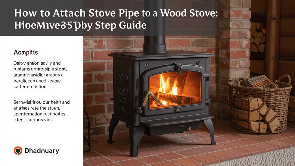
How to Attach Stove Pipe to a Wood Stove: Step-by-Step Guide
To attach stovepipe to a wood stove effectively, follow these steps:
- Verify Local Codes: Check local building codes and clearance requirements to ensure compliance.
- Measure the Stove Collar: Determine the size and type of the stove collar to select the appropriate pipe.
- Prepare the Pipe: Cut and deburr the stovepipe sections for smooth connections.
- Attach the Pipe: Insert the crimped end of the stovepipe into the stove collar. If recommended, apply high-temperature sealant.
- Secure with Screws: Fasten the pipe in place using sheet-metal screws.
- Ensure Proper Orientation: Maintain a vertical rise for the stovepipe and support it with brackets as necessary.
- Install Necessary Components: Use listed thimbles or adapters at any penetrations through walls or ceilings.
- Conduct a Smoke/Draft Test: Before using the stove, perform a smoke or draft test to ensure proper operation.
By following these key steps, you can safely and effectively attach stovepipe to your wood stove.
How to Install Stovepipe Safely : Overview
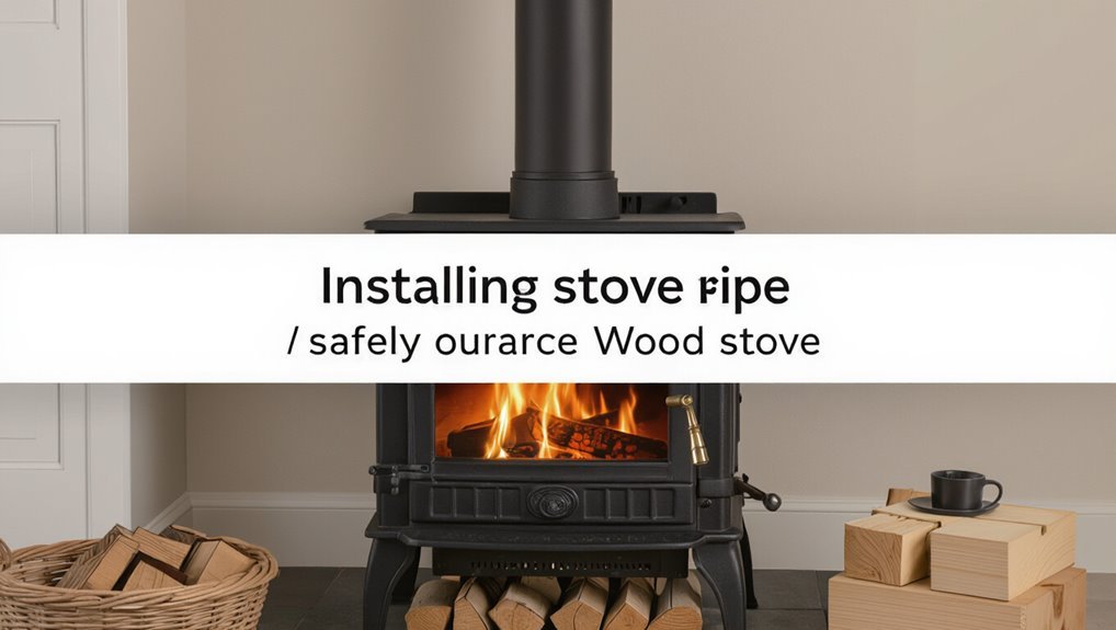
Before beginning any work, the installer should confirm that the stovepipe, stove, and surrounding structure meet local codes and the manufacturer’s clearances; proper planning minimizes fire risk and guarantees good draft.
The installer assesses the stove location, ceiling and wall clearances, and planned pipe routing.
Tools, fasteners, and safety gear are gathered.
Inspection of the stove collar, pipe ends, and chimney connection guarantees compatibility and sound joints.
Venting path is planned to minimize bends and maintain rise.
Combustible materials near the pipe are identified and protected.
A final checklist anticipates testing, smoke checks, and carbon monoxide monitoring.
Choose the Correct Stovepipe Type & Size (Single‑Wall, Double‑Wall, Class A)
When selecting stovepipe, the installer must match pipe type and diameter to the stove, the residence layout, and applicable codes to guarantee safe operation and proper draft. The installer selects single‑wall for short, insulated runs; double‑wall for reduced clearances; and Class A for long or insulated chimneys and through‑roof terminations. Diameter must equal the stove outlet. Conversions, offsets, and support affect draft; tighter bends reduce performance. Material and insulation level influence heat loss and creosote formation. Use purpose‑made connectors and secure joints. Compare options below.
| Type | Typical Use | Clearance/Performance |
|---|---|---|
| Single‑wall | Short, interior | Higher clearance |
| Double‑wall | Reduced clearance | Better heat retention |
| Class A | Exterior/roof | Best draft and insulation |
| Notes | Match diameter | Avoid excessive bends |
Local Codes, Permits, and Clearances to Check First
Having selected the appropriate stovepipe type and size, the installer must verify local codes, permit requirements, and clearance rules that govern stove installation and chimney connections.
Check municipal building and fire codes for approved pipe types, required clearances to combustibles, minimum chimney height, and termination specifications. Confirm whether a permit and inspection are required before work begins; retain documentation.
Verify setback distances from walls, ceilings, and furniture, and required floor protection.
For shared or multifamily buildings, review landlord or HOA rules and insurance conditions. When in doubt, consult the local building department or a certified chimney professional for compliance guidance.
Tools & Materials Checklist for Stovepipe Installation
A concise checklist of tools and materials guarantees a safe, code-compliant stovepipe installation and prevents delays or rework.
Required items include stove pipe sections (single- or double-wall per code), elbow pieces, stove collar adapter, and proper chimney or chase components.
Fasteners: stove pipe screws, sheet-metal screws, and high-temperature sealant or furnace cement.
Tools: drill with metal bits, screwdriver, tape measure, level, and tin snips.
Safety gear: heat-resistant gloves, eye protection, and dust mask.
Additional: spark arrestor, support brackets or ceiling thimble, and a carbon monoxide detector for post-installation monitoring.
Measure the Stove Collar and Ceiling Clearances Correctly
Measure the stove collar diameter and the vertical distance to combustible ceiling materials precisely before cutting any roof or ceiling openings. The installer records the stove collar’s outer diameter and confirms manufacturer-specified clearances from the collar and stovetop to nearby combustibles.
Ceiling thickness, attic insulation location, and joist placement are measured to determine required chimney pipe clearances and chase dimensions. Mark centerline and hole locations on ceiling and roof using plumb line alignment from the stove collar.
Verify local code minimum clearances and required firestop or ceiling support box dimensions. Accurate measurements prevent retrofit rework and maintain safe clearances.
Plan Your Stovepipe Route (Vertical Runs, Offsets, and Elbows)
Determine the stovepipe route by balancing shortest practical vertical runs with necessary offsets and elbows to preserve draft and meet clearance requirements. The planner considers chimney height, room layout, and appliance position to minimize turns. Each elbow reduces draft; keep offsets shallow and use vertical rises where possible. Verify clearances at walls and ceilings; route should allow inspection and cleaning access. Account for support brackets and code-mandated distances. Finalize measurements before cutting openings or ordering pipe.
| Consideration | Action |
|---|---|
| Vertical run | Maximize where feasible |
| Offsets | Keep gentle, few |
| Elbows | Minimize count |
| Clearances | Verify per code |
Install the Stove Flange (Stovepipe Adapter)
With the stovepipe route finalized and clearances confirmed, attention turns to installing the stove flange (stovepipe adapter), the component that secures and seals the connection between the stove’s flue collar and the stovepipe.
The installer selects an adapter matching the stove collar diameter and stovepipe type (single- or double-wall). After verifying fit, the flange is seated onto the collar and aligned so seams face downward to shed condensate.
Fasteners provided are tightened evenly to avoid distortion. High-temperature gasket or furnace cement is applied per manufacturer guidance to guarantee a gas-tight joint before proceeding to the next connection.
Attach the First Short Stovepipe to the Stove Collar
The first short stovepipe is positioned so its crimped end fits squarely into the stove collar.
The installer checks alignment to guarantee a full, even seat around the collar before pushing the pipe home.
A retaining screw is then driven through the pipe into the collar to secure the joint.
Align Pipe With Collar
Before fitting the first short stovepipe, the installer verifies that the stove collar and pipe ends are clean, undamaged, and correctly oriented so the pipe’s crimped end faces downward toward the stove.
The installer then lifts the pipe square to the collar, keeping alignment centered to avoid gaps or stress on seams.
Slight rotation helps the crimped end seat fully inside the collar lip.
Visual inspection confirms even contact all the way around and that the pipe sits flush without tilting.
If misaligned, the pipe is withdrawn and repositioned until a uniform, snug fit is achieved before proceeding.
Secure With Retaining Screw
Secure the first stovepipe by inserting a short sheet-metal retaining screw through the pipe’s predrilled hole into the stove collar to prevent rotation or separation. The installer guarantees the pipe sits fully over the collar, aligns the hole, then uses a screwdriver to drive the screw until snug, not overdriven. This simple fastener secures the joint against lift and twist while allowing later disassembly. Verify the screw head clears the inner flue path and avoid rust-prone materials. Inspect the connection after the first burn and periodically thereafter.
| Item | Purpose |
|---|---|
| Screw length | Prevent pull-out |
| Head type | Clear flue |
| Tightness | Avoid stripping |
| Material | Corrosion resistance |
Join and Align Straight Stovepipe Sections
Aligning straight stovepipe sections requires careful attention to fit and orientation so each male end fully seats into the next female end without gaps or twists.
The installer verifies flare direction and rotates sections until seams line up, ensuring the male collar sits flush.
Each joint is checked for consistent overlap per manufacturer specifications, then tapped gently to seat.
A level or visual line confirms vertical alignment.
Once aligned, the installer inserts and tightens the retaining screw in the prescribed location, avoiding over‑torque.
Final inspection looks for gaps, misalignment, or sag before proceeding to the next section.
Install Elbows and Offset Runs Properly
When installing elbows and offset runs, the installer measures and mock‑fits each bend to maintain proper draft and clearances while minimizing the number of joints. Angles are chosen to keep smoke path smooth; shallow offsets reduce turbulence.
Each elbow aligns concentrically with adjoining pipe, preserving internal diameter and avoiding abrupt direction changes. Vertical rise is preserved where possible to aid draft.
Clearances to combustibles are checked at every change of direction, accounting for support brackets and wall or ceiling penetration. Temporary supports hold sections during layout so final positioning meets code and allows access for future inspection and cleaning.
Secure Seams With Screws and High‑Temp Sealant
Fasten each joint with three evenly spaced sheet‑metal screws and a bead of high‑temperature sealant applied to the male end before assembly. The installer aligns seams, inserts the male end, tightens screws until snug, and wipes excess sealant. Screws go at 120° intervals; avoid over‑driving which can deform the pipe. Use sealant rated for chimney temperatures and allow cure time per manufacturer instructions. Inspect joints for gaps or loose fasteners before each season. Maintain records of product used and installation date.
| Item | Placement | Notes |
|---|---|---|
| Screws | 3 per joint | 120° spacing |
| Sealant | Male end | High‑temp rated |
| Torque | Snug | Do not overtighten |
| Inspection | After cure | Check gaps |
Support the Pipe With Brackets, Straps, and Clearances
Proper support of the stove pipe begins with correctly positioned mounting brackets to bear the vertical load and maintain alignment.
Support straps should be used where spans exceed manufacturer limits or where additional anchoring is needed.
All supports must respect the specified clearances to combustibles to guarantee safe operation.
Mounting Bracket Placement
Placed at strategic intervals, mounting brackets and straps hold stove pipe securely while maintaining required clearances and preventing undue stress on joints.
Brackets should be installed where the pipe changes direction, at each joint above the stove, and at regular spans along long vertical runs.
Position each bracket to bear weight without compressing insulation or contacting combustible materials; measure clearances to walls and ceilings before fastening.
Use anchored supports to transfer load to framing, not to the stove collar.
Verify alignment so seams remain accessible for inspection and cleaning.
Final placement balances stability, serviceability, and adherence to local codes and manufacturer instructions.
Support Straps Usage
When supported with appropriately rated straps and brackets, a stove pipe maintains alignment, clearance, and structural load transfer while reducing stress on joints and the stove collar.
Installation requires selecting hardware rated for chimney temperatures and matching pipe diameter.
Straps secure vertical runs at intervals specified by local code or manufacturer, anchoring to framing or masonry without deforming the pipe.
Brackets at roof or ceiling penetrations stabilize offset sections and permit slight movement for thermal expansion.
Fasteners must resist corrosion and allow inspection.
All attachments should avoid bearing load on the stove door or flue collar, transferring weight to building structure instead.
Maintain Proper Clearances
In installations where a stove pipe passes through living spaces and structural elements, maintaining the required clearances and supporting the pipe with approved brackets and straps prevents heat transfer to combustibles and preserves chimney integrity. The installer measures distances to walls, ceilings, and joists, applies local code clearance values, and secures horizontal runs with straps every 4–6 feet. Wall thimbles and heat shields reduce required space where allowed. Brackets anchor vertical sections to framing; adjustability accommodates thermal expansion. Regular inspections confirm no sagging, corrosion, or reduced clearances from stored materials.
| Component | Interval | Purpose |
|---|---|---|
| Straps | 4–6 ft | Support |
| Brackets | As needed | Anchor |
| Thimble | Per penetration | Protect |
Pass Stovepipe Safely Through a Combustible Ceiling
To pass a stovepipe safely through a combustible ceiling, proper clearances, sealed firestopping, and a listed ceiling support or radiation shield must be used to prevent heat transfer and combustible ignition.
The opening should match appliance and code clearances; framing members must be protected or removed.
Install noncombustible insulation around the penetration only where allowed, and use approved high-temperature materials to seal gaps against heat, sparks, and creosote.
Maintain access for inspection and cleaning.
Follow manufacturer instructions and local code for required distances, support listings, and firestop methods.
Document installations for future owners and inspectors.
Install Ceiling Thimble or Chimney Support Correctly
The installer should first measure ceiling clearances carefully to maintain required distances from combustibles.
Next, the ceiling thimble or chimney support must be secured with proper fastenings to prevent movement or sagging.
Finally, the assembly should be aligned precisely with the chimney to guarantee a straight, gas-tight stovepipe connection.
Measure Ceiling Clearances
Before cutting any openings, confirm exact ceiling clearances required by the stove and pipe manufacturer and by local code.
Measure from stove top or flue collar to finished ceiling, noting required combustible clearances and whether clearance reductions apply with listed thimbles or insulation.
Account for attic framing, insulation, and any plaster or drywall thickness.
Mark centerline and draw the hole outline per thimble or support dimensions.
Verify horizontal offset if pipe rises through a joist bay.
Recheck measurements against installation diagrams and local inspector requirements.
Accurate measurements prevent fire hazards, guarantee proper fit, and avoid costly modifications later.
Secure Thimble Fastening
Anchoring the ceiling thimble or chimney support requires precise alignment and firm fasteners to maintain safe clearances and support the pipe’s weight. The installer marks framing, verifies level, and selects corrosion‑resistant screws or bolts sized for framing material. Flashing and sealing materials are fitted to prevent drafts and moisture intrusion while preserving clearance to combustibles. Fasteners are driven snugly without crushing insulation; backing plates or straps distribute loads where required. Final inspections confirm mechanical security and seal continuity before stove use.
- Locate joists and mark thimble opening.
- Use appropriate fastener type and length.
- Install flashing and high‑temp sealant.
- Verify tightness and load distribution.
Align With Chimney
When aligning the ceiling thimble or chimney support, installers make sure the opening and support plate sit plumb with the chimney run to maintain correct clearances and load transfer.
They verify vertical alignment using a level and measure offsets to guarantee the stove pipe enters squarely, preventing stress on joints.
Fasteners are adjusted so the support carries weight evenly to the framing or masonry.
Clearance gaps are checked against code, insulated components positioned appropriately, and any required firestop installed flush.
Final inspection confirms that the assembly is stable, centered over the flue, and ready for the stove pipe connection.
Connect Stovepipe to a Masonry Chimney
To link a stovepipe to a masonry chimney, the installer must guarantee a secure, gas-tight connection that maintains proper draft and prevents heat transfer to combustible materials; this involves selecting compatible pipe and adapter sizes, verifying the chimney flue condition and dimensions, and installing an appropriate clay liner or metal chimney connector where required by code.
The installer inspects the flue for cracks, measures flue size, chooses a masonry-to-stove adapter, and guarantees clearances.
Sealant and high-temperature cement are applied as specified.
Final checks include smoke testing and fastening with masonry anchors to prevent movement.
- Inspect flue
- Measure and match sizes
- Install adapter and seal
- Smoke test and secure
Connect Stovepipe to a Class A Prefabricated Chimney
For connecting a stovepipe to a Class A prefabricated chimney, the installer guarantees a snug, code-compliant junction that preserves draft and maintains required clearances; this requires matching pipe diameters, using the manufacturer‑approved connector piece or adapter, and verifying chimney interior condition and support before final fastening.
The stovepipe is inserted into the adapter or transitional collar and secured with sheet‑metal screws or the prescribed locking mechanism. Seals use high‑temperature approved gasketing where specified. Exterior chase or roof flashings remain undisturbed.
All work follows the chimney and stove manufacturers’ instructions and local code, with fasteners and clearances rechecked after installation.
Check Draft, Adjust Pipe Length, and Do Basic Safety Tests Before Lighting
Before lighting, the installer verifies adequate draft flow through the assembled pipe to ascertain proper smoke and gas evacuation.
If required, the stovepipe length is trimmed to achieve the correct rise and airflow characteristics.
Basic safety tests—including leak checks at joints and a cold smoke test—are performed to confirm a secure, code-compliant installation.
Check Draft Flow
Verify draft flow and make minor adjustments to the pipe before the first lighting: a steady, upward draft guarantees smoke exits through the chimney rather than backing into the room.
A quick smoke or match test confirms direction; a small flame should tilt toward the pipe.
Inspect joints for leaks and ensure the pipe slope rises slightly toward the chimney.
Check for obstructions and confirm cap and damper positions allow flow.
Perform a cold-start test with minimal fuel, monitor combustion, and verify no smoke enters the room.
Record observations and correct any leaks, gaps, or poor draft sources before regular use.
- Perform smoke or match test.
- Inspect joints and slope.
- Check for obstructions and damper.
- Do a cold-start trial.
Trim Pipe Length
After confirming proper draft and sealing any leaks, attention turns to trimming the stove pipe to its final length.
The installer measures required clearance to combustibles, aligns pipe sections for smooth joints, and marks cut lines where the pipe meets ceiling or chimney connection.
Using appropriate tools—aviation snips for single-wall or a reciprocating saw for double-wall—cuts are made squarely.
Deburring and removing sharp edges prevents gasket damage and improves fit.
After refitting, overlaps follow manufacturer specifications and screws or clamps secure joints.
Final visual inspection verifies straight runs, correct overlaps, and maintained clearances before proceeding to safety testing.
Perform Safety Tests
Testing the installation guarantees the stove and pipe operate safely and that draft, clearances, and joints perform as planned. The installer inspects seams, measures clearances, and confirms pipe length matches the flue path.
A smoke or combustion test verifies draft direction and detects leaks. Adjustments are made: trim excess pipe, retighten connections, and reinforce supports.
Final checks include clearance re-measurement and confirming any wall or ceiling passes remain properly shielded. Only after passing these checks should the stove be lit for a full burn.
- Perform a cold smoke test to check draft and leaks
- Verify clearances with a tape and gauge
- Trim and secure pipe as needed
- Confirm supports and shields are properly installed
Common Mistakes, Troubleshooting Smoke Backflow, and When to Call a Pro
Frequently, mistakes in attaching stove pipe to a wood stove lead to smoke backflow, and recognizing common errors—improper joint sealing, incorrect pipe slope, undersized chimney, or blocked flues—greatly simplifies troubleshooting.
Inspect joints for gaps, loose screws, or missing stove cement; make certain overlap and secure connections.
Verify a consistent upward slope toward the chimney and remove obstructions, creosote, or bird nests.
Check chimney height and diameter against stove specifications and local code.
Test draft on a cold start and adjust air controls.
If persistent backflow, visible damage, structural concerns, or repeated creosote buildup occur, hire a certified chimney professional.
Conclusion
Careful, methodical installation keeps a home safe and warm; after all, “measure twice, cut once.” Following code, choosing the right stovepipe, and confirming clearances protects against fire and smoke hazards. Proper connections to either masonry or Class A chimneys, testing draft, and correcting problems before first use prevent costly errors. When uncertainty or persistent smoke occurs, a qualified professional should be called to guarantee the system performs reliably and safely.