How Deep Is a Sewer Pipe? Expert Guide to Typical Depths & Codes
Sewer pipe depth typically ranges from 18 inches to 20 feet, depending on function, climate, and local codes. Here are the key takeaways:
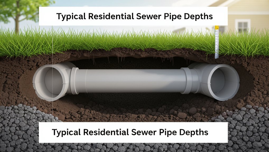
- Residential Laterals: Generally buried 18 inches to 5 feet below finished grade to protect against frost and load.
- Building Sewers and Service Lines: Depth varies based on basement elevation and can be deeper than residential laterals.
- Municipal Mains: Usually installed at depths of 6 to 20 feet to maintain proper slope and avoid existing utilities.
- Factors Affecting Depth: Soil type, groundwater levels, and traffic loads can influence the required cover and material choices.
Understanding these depth ranges and considerations will help ensure proper installation and compliance with local codes.
What People Mean by “How Deep Is a Sewer Pipe?
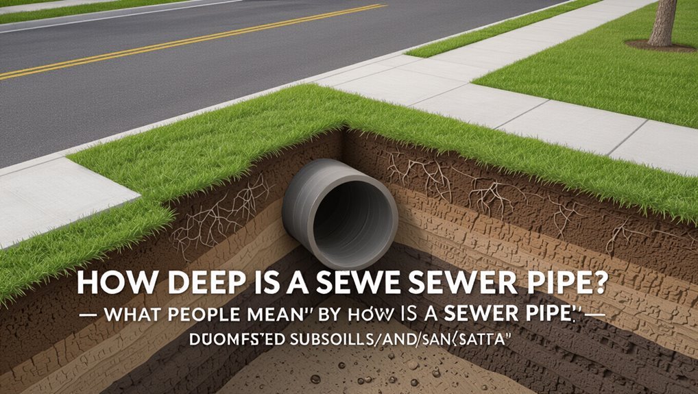
What do people mean when they ask “How deep is a sewer pipe?”—they typically seek the vertical distance from the ground surface to the pipe’s top or centerline, but the phrase can also refer to code-required minimum depths, frost-protection depth, or the elevation relative to nearby structures and utility lines.
Observers may intend design depth for gravity flow, cover needed for vehicular loads, or the invert elevation for connection. Contractors, inspectors, and homeowners interpret depth differently: plans use centerline/invert, codes specify minimum cover, and engineers balance slope, frost risk, and conflicts with other utilities when determining appropriate placement.
Quick Answer: Typical Sewer Pipe Depths
Typical residential sewer pipes are buried between 18 inches and 5 feet below finished grade, though municipal mains and trunk lines commonly lie deeper—often 6 to 12 feet—to accommodate larger diameters, gravity flow, and utility coordination.
Depth varies with climate, local codes, terrain, and connection point elevations. Shallow pipes risk freezing or damage; deeper installations increase excavation cost and require permit review.
Professionals assess slope, downstream invert, and existing utilities before specifying depth. Homeowners should consult local public works or a licensed plumber for site-specific guidance rather than relying solely on general ranges.
- Climate impacts minimum bury depth.
- Codes set legal minima.
- Gravity and invert dictate placement.
Typical Depths for Single‑Family Builds
For single‑family residential construction, sewer pipe depths are generally guided by the need to balance frost protection, ease of connection to the building drain, and minimizing excavation costs. Typical ranges place building sewer pipes between 18 inches and 4 feet below finished grade, deeper where frost or site slope requires. Slopes, fixture counts and local code influence invert elevation. Contractors often verify utility maps and obtain permits before trenching. Shallow profiles may need insulation or heated runs. Designers prioritize gravity flow; lifts or pumps are used only when necessary. Site-specific conditions determine final depth selection.
| Condition | Typical Depth |
|---|---|
| Frost risk low | 18–24 in |
| Frost risk high/terrain | 36–48 in |
| Basement connection | Varies (>48 in) |
Typical Municipal Sewer Main Depths
Municipal sewer main depths commonly range from 6 to 20 feet below finished grade, determined by hydraulic requirements, frost protection, road and utility clearances, and the need to maintain gravity flow.
Placement balances peak flow capacity, access for maintenance, and surrounding infrastructure constraints; deeper mains increase hydraulic capacity but raise construction and safety costs.
Designers follow local codes, soil conditions, and future development plans when fixing invert elevations.
Attention to manhole spacing, drop structures, and protection from vehicle loads also guides depth decisions.
Coordination with stormwater, water, and gas utilities prevents conflicts and costly relocations.
- Capacity vs. cost
- Frost and cover
- Utility coordination
Which Depth Matters: Lateral, Building Sewer, or Main?
Attention to which segment of the sewer system is being measured affects compliance and repair responsibilities.
Comparisons between lateral and building sewer depths determine homeowner versus utility obligations, while contrasts between the building sewer and the municipal main influence required invert elevations and connection methods.
Clear distinctions among these segments guide design, permitting, and maintenance decisions.
Lateral Versus Building Sewer
Determining which sewer depth governs a property’s connection requires distinguishing the lateral, the building sewer, and the main: the lateral runs from the main to the property line, the building sewer extends from the property line to the structure, and the main is the municipality’s trunk line.
Responsibility, code limits, and inspection points differ: laterals often fall under utility jurisdiction and must meet depth set by mains; building sewers follow local plumbing codes and frost-depth or slope requirements; the correct depth for service depends on which segment controls drainage, maintenance access, and liability.
- Ownership: defines who enforces depth rules.
- Code: prescribes minimum slope and burial.
- Access: influences inspection and repair depth.
Building Sewer Versus Main
A clear distinction between the building sewer and the main determines which depth controls a property’s connection: the building sewer is the privately owned run from the property line to the structure, while the main is the publicly owned trunk line in the street or easement.
Which depth governs depends on responsibility and code: the building sewer must meet local plumbing code minima for frost protection and slope, whereas the main follows municipal standards and cover requirements.
When elevations conflict, the lower invert usually dictates connection details. Permits clarify jurisdiction, and utility records locate mains; contractors coordinate to reconcile grades and guarantee compliant ties.
What Controls Sewer Depth (Overview)
Because sewer depth must balance gravity flow, frost protection, and existing site constraints, it is governed by a small set of technical and regulatory factors.
Engineers and inspectors consider soil frost depth, groundwater level, required pipe cover for loading, existing utilities, and local code minima.
Practical installation limits, access for maintenance, and connection elevations at buildings and mains constrain final grade.
Cost and trenching methods influence how deep contractors will excavate.
The result is a negotiated depth that meets hydraulics, durability, and code while minimizing disruption and expense.
- Soil and frost conditions
- Groundwater and loading
- Codes and existing utilities
Minimum Slope Requirements for Sewer Pipes
Minimum slope requirements vary with pipe diameter, since larger pipes can carry flow at lower slopes while smaller pipes need steeper pitch to prevent solids settling.
Typical manufacturer and code tables give minimum slopes by pipe size, which should be referenced when planning runs.
Calculating proper pitch requires using the chosen pipe’s minimum slope, the run length, and elevation change to guarantee self-cleansing velocity.
Minimum Slope By Pipe Size
Proper pipe slope depends on pipe diameter and the nature of the wastewater flow; engineers specify minimum gradients to guarantee solids remain in suspension while preventing excessive velocity that could erode the conduit.
Guidance typically ties minimum slope to nominal pipe size: smaller diameters require higher gradients to maintain self-cleansing velocities, while larger mains can function with gentler pitches.
Typical reference values are often published in plumbing codes and engineering tables; designers select the least slope meeting hydraulic and structural criteria.
Practical factors—peak flow, solids content, and upstream connections—affect final choice and maintenance planning.
- 3‑inch to 6‑inch: higher minimums
- 8‑inch to 12‑inch: moderate minimums
- 15‑inch and larger: low minimums
Calculating Proper Pitch
Calculating the correct pitch for a sewer pipe requires balancing hydraulic needs with practical site constraints: designers use pipe diameter, expected flow rates, and solids characteristics to determine the minimum slope that maintains self-cleansing velocity without inducing erosion.
Engineers reference code tables and Manning’s equation to translate flow and roughness into slope, verifying that minimums prevent sedimentation under low-flow conditions while avoiding excessive velocities that can damage joints.
Field adjustments consider pipe material, alignment changes, and future loadings. Final grades are documented in plans, with inspection and testing ensuring installed slopes meet design intent and regulatory minimums.
Frost Line and Minimum Burial Depth
Frost depth varies by region and determines how deep sewer pipes must be buried to avoid freezing; local climate maps and building codes specify the required frost line for design and installation.
Designers set minimum burial depth a few inches below the frost line to prevent ice formation in pipes and maintain flow.
Soil insulation, pipe material, and ground cover influence practical depth choices. In cold climates, deeper trenches or additional insulation are common.
Proper placement reduces maintenance, blockages, and pump failures while ensuring longevity.
- Prevent freezing and maintain flow
- Account for soil and insulation
- Minimize service and repairs
Local Code Limits and National Standards
After establishing required burial depths to prevent freezing, attention turns to how local building codes and national standards govern those requirements.
Jurisdictions adopt minimum depths reflecting climate, utility coordination, and public safety; municipalities may mandate deeper burial than national model codes.
Model documents—such as the International Plumbing Code and ASTM standards—set installation practices, pipe materials, and testing criteria that influence allowable depths.
Compliance depends on permit inspections and engineering approvals; where conflicts arise, local ordinances typically prevail.
Designers consult both sources, apply the stricter requirement, and document rationale to satisfy inspectors and guarantee long-term serviceability and regulatory compliance.
Soil Type, Groundwater, and Load Effects
Because soil characteristics, groundwater presence, and surface/vehicular loads directly affect pipe performance and required cover, designers evaluate them together when setting burial depth and installation methods.
Soil type determines bedding, frost risk, and bearing capacity; cohesive clays may need deeper cover or stabilization, while dense sands support shallower installations. Groundwater raises buoyancy, corrosion risk, and can require anchors or deeper embedment and drainage.
Load effects from nearby structures transmit through soils, altering stress on the pipe body. Combined assessment guides material selection, joint type, and backfill specifications to ascertain long-term serviceability.
- Evaluate soil-bearing capacity and frost susceptibility.
- Assess groundwater level, chemistry, and seasonal fluctuation.
- Specify bedding, backfill, and corrosion mitigation accordingly.
Traffic Loads and Required Cover Depth
Traffic loads are categorized by vehicle type and frequency to determine the stresses transmitted to buried pipes.
These classifications inform required minimum cover depths to prevent pipe deformation or failure under load.
Pavement thickness and structural composition interact with cover requirements, often allowing reduced burial depth where roadway layers adequately distribute loads.
Traffic Type Classification
When classifying traffic types for sewer pipe installation, load intensity and frequency determine the minimum cover depth required to protect the conduit and guarantee long-term performance.
Classification separates pedestrian, light vehicular, and heavy vehicular zones, aligning expected axle loads, repetition, and construction variables with protective measures. Designers reference local codes and utility standards to assign classes; classifications influence bedding, pipe material choices, and inspection regimes.
Risk factors like temporary construction traffic or future roadway upgrades are noted. Clear assignment prevents under- or over-design, optimizes cost, and reduces maintenance.
Typical categories include:
- Pedestrian and bicycle
- Passenger vehicles and service trucks
- Heavy trucks and industrial loads
Load-Driven Cover Requirements
Although surface loads vary by route and usage, design practice ties minimum cover depth directly to expected axle loads and their frequency.
Engineers select cover so soil and pavement distribute wheel loads, preventing pipe crushing and limiting deflection. Standards reference equivalent single axle loads, traffic classification, and design life to derive required earth cover or protective concrete slabs.
Material strength, pipe stiffness, bedding type, and depth-to-traffic interact in calculations. Where heavy frequent truck traffic occurs, cover requirements increase or special protective measures are specified.
Proper documentation of load assumptions and safety factors guarantees compliant, durable buried sewer installations.
Pavement Thickness Interaction
Because pavement thickness directly affects how wheel loads are spread into the subgrade, its design is a primary factor in determining required sewer cover depth.
Pavement stiffness, layer composition, and expected axle loads change bending moments in buried pipes; thicker, stiffer pavements can reduce required cover by distributing stresses away from the pipe.
Engineers evaluate pavement sections, traffic loading, and soil support to set minimum burial depths that prevent deformation and fatigue. Coordination with pavement design prevents over- or under-protection of conduits.
Considerations include future resurfacing and safety factors for unexpected heavy loads.
- Pavement stiffness
- Traffic intensity
- Resurfacing allowance
Pipe Materials by Burial Depth (PVC, Clay, Ductile Iron)
Different pipe materials require specific burial depths to balance structural support, frost protection, and load-bearing capacity.
PVC often permits shallower cover due to high strength-to-weight ratio and flexible joint design; typical residential sewer cover ranges from 12 to 36 inches, increasing under roadways.
Clay pipe, more brittle, generally requires greater depth or protective measures to avoid concentrated loads, commonly 24 inches minimum and deeper in trafficked areas.
Ductile iron, robust against loads and impact, can be buried shallower than clay under heavy loads but is frequently placed at standard depths of 18–36 inches to guarantee corrosion allowance and mechanical protection.
Bedding, Backfill, and Compaction Requirements
Selection of appropriate bedding material is critical to distribute loads and support the pipe per design specifications.
The required compaction depth and method depend on pipe type, bedding class, and anticipated surface loads to guarantee long-term stability.
Proper coordination of bedding, backfill, and compaction reduces settlement and prevents pipe deformation.
Bedding Material Selection
Bedding material plays a critical role in supporting sewer pipe integrity by providing uniform bearing, preventing point loads, and facilitating proper load transfer to surrounding soil.
Selection emphasizes particle size, gradation, and absence of deleterious material to guarantee cradle support and minimize differential settlement.
Permeability and frost susceptibility guide choices in cold climates; corrosion resistance matters near aggressive soils.
Manufacturers’ recommendations and local codes narrow acceptable materials: crushed stone, coarse sand, or controlled low-strength material (flowable fill) in specific applications.
Proper placement and thickness (not compaction depth) complete bedding performance.
- Crushed stone: uniform angular particles for stable contact.
- Coarse sand: conforms well around pipe haunches.
- Flowable fill: used where shaping or void filling is required.
Compaction Depth Requirements
Because proper layer thickness and compactive effort directly determine long-term pipe performance, compaction depth requirements specify the thickness of bedding, haunching, and backfill lifts and the degree of densification necessary to prevent settlement, pipe deformation, and loss of support.
Typical guidance calls for dense-graded bedding 4–6 inches under pipe invert, haunch material tampered in 6–12 inch lifts compacted to specified relative density, and backfill placed in 8–12 inch lifts with compaction to 90–95% of modified Proctor where traffic loads occur.
Fine-grained soils may require thinner lifts and higher energy compaction; testing and inspection verify compliance.
Shallow Sewer Installations: When Allowed
When local conditions or practical constraints prevent meeting standard cover depths, jurisdictions sometimes permit shallow sewer installations under strict criteria: the pipe material and stiffness must suit reduced burial, ground and traffic loads must be evaluated, frost risk addressed, and access for maintenance secured.
Approval hinges on documented engineering justification, protective bedding and backfill specifications, and limitations on imposed surface loads. Permits may require monitoring, load-rated surfacing, or use of stronger pipe classes.
Shallow installations are typically reserved for short runs, low-traffic areas, or temporary systems where risks are minimized and mitigation is enforced.
- Engineering justification
- Load and bedding controls
- Maintenance access
Frost Protection and Shallow Burial Techniques
If frost depth threatens sewer performance, designs for shallow burial must combine thermal protection, structural reinforcement, and careful route planning to prevent freezing and maintain serviceability.
Practices include minimizing slope reversals, avoiding depressions that trap cold air, and maintaining continuous flow velocity to resist ice formation.
Mechanical measures involve increased pipe diameter for heat retention and selecting materials with higher frost resilience.
Burial beneath heated slabs or within building footprints reduces risk.
Access points and cleanouts should be placed for easy thawing and inspection.
Maintenance plans must include seasonal monitoring and rapid response procedures when low-flow or freezing conditions are observed.
Protection Sleeves, Insulation, and Liners
While routing and burial techniques reduce freeze risk, protection sleeves, insulation, and internal liners provide targeted barriers against thermal loss, mechanical damage, and infiltration.
They localize protection where shallow runs cross driveways, pavements, or hand-exposed trenches, and can extend service life without deeper excavation.
Sleeves allow pipe replacement; rigid insulation minimizes frost penetration; and liners control leaks and corrosion.
Selection depends on soil, load, temperature, and access.
Proper sealing at joints and end boots preserves thermal continuity and prevents groundwater entry.
Installation follows manufacturer and code specifications to guarantee performance and inspectability.
- Sleeves for access and isolation
- Insulation for thermal resistance
- Liners for leak mitigation
How Topography and Grade Change Pipe Depth
Topography and grade shifts dictate how deep sewer lines must be set to maintain flow, avoid excessive excavation, and prevent freezing or backflow.
Sloping terrain requires deeper trenches on high ground or stepped profiles to preserve minimum slope for gravity drainage; valleys may allow shallower placement.
Rock outcrops or high groundwater force alternative alignments or deeper excavation and may necessitate pumps or relays.
Urban sites balance hinterland grades against existing utilities, rights-of-way, and surface restoration costs.
Designers evaluate longitudinal profiles, erosion risks, and constructability to choose depths that meet hydraulic requirements while minimizing cost and service disruption.
How to Calculate Invert Elevation and Depth
The section explains invert elevation as the lowest interior point of a sewer pipe relative to a known datum.
It outlines methods for measuring pipe depth from ground surface to that invert.
It then shows how to calculate elevation differences between inverts to establish proper grade.
Invert Elevation Defined
Invert elevation specifies the vertical position of a sewer pipe’s internal lowest point relative to a fixed datum, typically sea level or a project benchmark. It informs hydraulic gradient, flow capacity, and alignment with manholes and laterals.
Calculations use surveyed datum elevations minus measured pipe internal depth; allowances account for pipe diameter and invert slope. Clear documentation guarantees coordination with grading and stormwater systems and compliance with design standards.
- Use surveyed benchmark elevation and measured vertical offsets to compute invert.
- Subtract internal pipe radius when converting outside rim or crown elevations.
- Record slope and tolerance for hydraulic verification.
Measuring Pipe Depth
Several straightforward measurements are combined to determine a sewer pipe’s invert elevation and depth: a known benchmark elevation, vertical offsets from survey shots or level readings to the pipe crown or rim, and the pipe’s internal geometry.
The process records benchmark elevation, measures vertical staff or rod readings at manholes or cleanouts, and notes distance from crown or rim to invert using pipe diameter and wall thickness or manufacturer tables.
Subtracting the offset from the surveyed crown/rim elevation yields invert elevation; depth equals ground surface elevation minus invert elevation.
Results should be checked for consistency, documented, and referenced to the project datum.
Calculating Elevation Difference
When establishing invert elevation and pipe depth, calculate the elevation difference by subtracting the measured vertical offset from the surveyed crown or rim elevation to obtain the invert elevation.
The process requires precise survey data, consistent reference datums, and verification of offsets at multiple points along the run. Convert units as needed and record measurement uncertainty.
Determine pipe depth by subtracting the invert elevation from finished grade elevation, accounting for bedding and cover requirements. Use trenches’ slope to reconcile discrepancies and guarantee hydraulic grade line integrity.
- Confirm datum and units
- Measure crown/rim and offset carefully
- Compute invert, depth, and tolerances
How to Measure Sewer Depth on Your Property
Measuring sewer depth on a property requires locating the sewer line access points, choosing an appropriate measurement method, and recording depths relative to a fixed reference such as ground level or finished floor elevation.
The process typically uses a tape measure in excavations, a graduated probe through cleanouts, or sonar/radar instruments for nondestructive checks. Measurements should note horizontal offsets and invert elevation (pipe interior lowest point).
Record datum, measurement device, and operator. For sloped runs, measure at multiple points to calculate grade.
Safety precautions—shoring, ventilation, PPE—are mandatory when entering trenches or exposing pipes. Store results with plans for future reference.
How a Plumber or Locator Finds Your Sewer Line
A plumber or locator typically begins by running a camera through the sewer to visually confirm pipe condition and route.
If precise depth or position is required, electromagnetic locating equipment is used to trace the camera head or a sonde and map the line underground.
These complementary methods together establish both the pipe’s layout and its depth.
Camera Inspection
Tecnicians deploy a flexible video camera into the sewer line to visually trace its path, locate blockages, and confirm depth and orientation.
The camera feed documents pipe material, joint condition, root intrusions, and offsets while the operator notes distance markers and surface reference points.
Portable monitors display live images; recordings provide evidence for repair decisions. Access is via cleanouts or manholes; small-diameter lines may require specialized heads.
Weather and flow affect clarity, so jets or plugs may be used to improve visibility. Results guide excavation depth estimates and repair planning without invasive probing.
- Precise visual mapping
- Condition assessment
- Excavation planning
Electromagnetic Locating
When visual inspection alone cannot reliably trace a buried sewer, electromagnetic locating provides a noninvasive way to pinpoint a pipe’s route and depth by coupling a transmit signal to the line and tracing it with a receiver aboveground.
Technicians attach a transmitter to accessible cleanouts or induce a signal on metallic portions, then walk a grid with a handheld receiver to map signal strength and direction. Advanced units calculate depth from signal geometry.
This method distinguishes parallel utilities, identifies offsets and bends, and guides targeted excavation.
Accuracy depends on signal coupling, pipe material, soil conditions, and operator skill; verification with camera or test digs is common.
Using Utility Records and As‑Builts to Find Depth
Although utility records and as‑builts can vary in completeness, they often offer the most direct starting point for estimating sewer pipe depth.
Agencies, engineering firms, and contractors keep plans showing pipe sizes, stationing, and, sometimes, invert elevations; review these first to establish expected depths and discrepancies.
Verify document dates and revision notes, and compare multiple sources to spot inconsistencies.
When available, digital GIS layers may provide coordinate-linked depth attributes that speed validation.
If records conflict with field observations, treat as guidance rather than definitive.
- Confirm document provenance and revision history.
- Cross‑reference multiple plans and GIS data.
- Use records to prioritize field verification.
Basement Plumbing Basics and Invert Elevation
Because basement plumbing connects lower-level fixtures directly to the municipal sewer or building lateral, understanding fixture locations, trap and vent arrangements, and outlet invert elevations is essential to prevent backflow and maintain proper drainage.
Basement drains require careful slope, proper trap sizing, and venting to avoid siphonage and odor. Invert elevation—the lowest point inside a pipe—determines how high incoming sewer must be relative to fixtures to guarantee gravity flow and to set necessary backwater valves.
Accurate measurement of invert elevations guides pipe pitch, rim elevations of floor drains, and connection points to the building sewer, minimizing backups and guaranteeing code compliance.
Septic Laterals vs. Municipal Sewer Depth
While both septic laterals and municipal sewer mains serve the same basic purpose of conveying wastewater away from a building, they differ markedly in design depth, frost protection, and maintenance considerations.
Septic laterals are typically shallower, placed to allow gravity flow to a septic tank and drainfield, with insulation or deeper burial where frost is a concern.
Municipal mains are deeper to maintain service grades, access manholes, and prevent freezing, and follow stricter utility standards.
Ownership, inspection frequency, and repair responsibility also contrast, affecting design choices and required clearances.
- Ownership and maintenance responsibility
- Frost protection and burial depth
- Inspection and access requirements
Typical Depths: Storm Sewers vs. Sanitary Sewers
Depths for storm sewers and sanitary sewers commonly differ due to their functions, flow characteristics, and required connections: storm sewers are typically shallower, designed to collect surface runoff and tie into catch basins and roadside inlets, while sanitary sewers are placed deeper to serve building lateral connections, maintain gravity flow from fixtures, and avoid conflict with surface loads and other utilities.
Typical storm sewer invert depths range from 12 to 48 inches below grade in residential areas, deeper along major corridors.
Sanitary sewers often range from 4 to 12 feet or more, depending on building elevations, slope requirements, and downstream system elevations.
Manholes, Inspection Chambers, and Depth Placement
Shifts in invert elevations between storm and sanitary systems often dictate the placement and design of access points such as manholes and inspection chambers.
Access structures align with flow gradients, provide vertical drops where needed, and accommodate maintenance clearances; depth placement balances frost protection, cover requirements, and surface loadings.
Materials and benching must match expected depth and flow velocity to prevent sedimentation. Local codes govern spacing, rim elevations, and safety features.
Designers locate inspection chambers for shallow connections and use manholes at changes in grade, pipe size, or alignment to guarantee safe, accessible operation.
- Inspection chamber placement
- Manhole spacing logic
- Rim and invert coordination
Special Cases: Hillside, Wetland, and Rock Excavations
Because terrain and substrata vary dramatically, pipeline design must adapt to hillside gradients, wetland soils, and rock excavations with targeted strategies for stability, access, and hydraulic performance.
On hillsides, slope stabilization, erosion control, and staged anchoring prevent pipe movement; trenchless methods or embedded bedding mitigate differential settlement.
In wetlands, buoyancy prevention, corrosion-resistant materials, and minimal excavation footprints protect ecology while maintaining cover and slope.
Rock excavations require controlled blasting or rock-cutting, precision invert profiling, and specialized bedding to avoid point loads.
Design integrates geotechnical reports, construction constraints, and maintenance access to guarantee long-term serviceability under site-specific conditions.
When to Raise or Lower a Building Sewer (Criteria)
Determining whether to raise or lower a building sewer hinges on maintaining proper elevation and slope to guarantee self‑cleansing flow without creating backups.
Physical obstructions, required clearances from foundations or utilities, and site-specific constraints may force adjustment of the invert elevation.
These criteria guide whether rerouting, deeper trenching, or raising the connection is the most practical solution.
Elevation And Slope
Elevation and slope of a building sewer govern whether the line must be raised or lowered to guarantee proper drainage and maintain self-cleansing velocity.
Engineers assess existing grade, pipe invert, and fixture elevations to determine adjustments. Minimum slope prevents solids deposition; excessive slope causes separation and flow issues.
Decisions weigh available cover, frost protection, and connection to public sewer inlets. Raising or lowering follows calculated invert changes, manhole placement, and local code slope minima/maxima.
Cost, excavation depth, and utility conflicts influence choice. Clear documentation facilitates compliance and future maintenance access.
- Calculate required slope vs. available grade.
- Balance cover depth and frost risk.
- Coordinate with mainline invert and codes.
Obstruction And Clearance
One key factor prompting a sewer raise or drop is the presence of subsurface obstructions — utilities, rock ledges, or structural footings — that conflict with the required pipe invert or cover.
Decisions weigh required slope, minimum cover for frost protection, and vertical separation from other utilities per code. Solutions include raising the sewer via short risers, lowering by localized excavation or rock removal, or rerouting to avoid conflicts.
Structural impacts, maintenance access, and cost are evaluated alongside permit constraints. Final placement must maintain flow velocity, prevent backflow, and satisfy agency clearance distances to potable lines and storm systems.
Alternatives When Gravity Can’t Reach the Main (Pumps?)
When gravity alone cannot carry wastewater to the municipal main, mechanical pumping systems provide the necessary lift and conveyance; these systems range from simple ejector pumps in individual buildings to sewage grinder pumps and lift stations that handle large flows and solids.
Selection depends on flow, solids, redundancy, and maintenance capacity. Properly sized wet wells, alarms, check valves, and access for service reduce backups. Energy reliability and odor control also matter. Designers balance upfront cost against operational risk and regulatory limits on discharge. Insight into lifecycle costs guides optimum choice for sites where gravity sewers are impractical.
- Grinder pump systems for low‑volume, solid‑handling service
- Pressure sewer networks using private pumps to a pressure main
- Lift stations with duplex pumps, wet wells, and controls
Permitting Steps Tied to Proposed Depth Changes
The permitting steps for proposed sewer depth changes begin with a complete permit application that specifies the proposed depth and supporting documentation.
Required soil and depth studies must accompany the application to demonstrate stability, groundwater interaction, and constructability.
Final approval follows agency review and on-site inspections to verify compliance with approved plans and conditions.
Permit Application Requirements
Because proposed changes to sewer pipe depth alter hydraulic performance, groundwater interaction, and excavation risk, permit applications must explicitly document the new depth, supporting calculations, and mitigation measures.
The submission should reference applicable codes, indicate impacts on downstream flows, and describe temporary and permanent shoring, dewatering, and utility protection.
Plans must be stamped by a licensed engineer when structural, hydraulic, or public-safety risks increase.
Review timelines and fees vary by jurisdiction; applicants should pre-check local checklists and schedule pre-submittal meetings to reduce revisions and delays.
- Engineered calculations and drawings
- Risk mitigation and construction methods
- Agency-specific checklist and fees
Soil And Depth Studies
Although site-specific soil conditions and proposed sewer depths directly affect excavation stability and pipeline performance, permitting requires systematic soil and depth studies that quantify those effects and inform mitigation.
Agencies typically request geotechnical reports, test borings, groundwater monitoring, and slope stability analyses tied to depth variations. Engineers correlate bearing capacity, settlement potential, and soil corrosivity with proposed invert elevations to specify bedding, backfill, and dewatering needs.
Depth increases may trigger additional requirements: deeper shoring, rock cutting plans, or alternative alignment assessments. Permit reviewers use these studies to set conditions, required corrective measures, and monitoring during construction to protect infrastructure and public safety.
Inspection And Approval Process
When proposed sewer depths deviate from initial plans, permitting agencies initiate a coordinated inspection and approval sequence that links document review, field verification, and conditional permits to depth-specific risks.
The process requires submittal of revised plans, engineered calculations for loading and slope, and geotechnical reports. Inspectors schedule staged field checks during excavation, bedding, and backfill.
Conditional approvals may impose monitoring, depth limits, or alternative materials. Final sign-off follows verification that installed depths meet approved tolerances and that mitigation measures function.
Record drawings and as-built certifications close the permit.
- Submittal and technical review
- Staged field inspections
- Conditional approvals and final sign-off
Coordinating Sewer Depth With Other Utilities
Coordinating sewer depth with nearby utilities requires precise planning to prevent conflicts, minimize excavation, and guarantee safe maintenance access.
Planners reference utility maps, as‑built records, and subsurface surveys to establish vertical separations from water, gas, electric, telecom, and storm lines. Minimum clearances follow codes and manufacturer guidance; offsets accommodate bedding, frost protection, and future repairs.
Where overlaps occur, designers adjust alignment, use deeper profiles, protective encasements, or reroute noncritical conduits. Coordination meetings and permit reviews secure stakeholders agree on elevations and access points.
Accurate documentation and markouts during construction reduce risk of strikes and costly rework.
Trenching Practices for Shallow vs. Deep Installs
Because trenching requirements change markedly with depth, crews adopt distinct excavation methods, shoring, and safety measures for shallow versus deep sewer installations.
For shallow trenches, control of surface traffic, minimal benching, and quick backfill reduce exposure and settlement risks.
Deep installs often require staged excavation, sloping, and engineered dewatering to manage groundwater and maintain grade.
Material handling differs: short hauls and compactors for shallow, mechanical lifts and staged spoil for deep.
Inspection frequency increases with complexity.
Coordination with utilities and permits is routine regardless of depth, but planning intensity scales with excavation depth and site constraints.
- Shallow: speed, minimal equipment, quick restoration
- Deep: staged work, dewatering, heavy lifting
- Both: utility coordination, inspections, permit compliance
Shoring, Safety, and Deep Excavation Risks
Although deeper excavations increase capacity for large-diameter sewer runs, they also introduce significant shoring and safety challenges that must be addressed before work begins. Risks include collapse, groundwater ingress, hazardous atmospheres, and vehicular loading; mitigations require engineered shoring, competent person oversight, access/egress plans, and continuous monitoring. Compliance with OSHA and local codes reduces liability and injury. Emergency response readiness and worker training are essential. Geotechnical input guides excavation geometry and shoring type; dewatering and utility support further complicate controls.
| Hazard | Control | Responsibility |
|---|---|---|
| Collapse | Engineered shoring | Contractor |
| Groundwater | Dewatering | Geotech engineer |
| Atmosphere | Gas testing | Site supervisor |
Cost Differences: Shallow vs. Deep Installation
Shallow installations generally reduce labor and equipment costs by requiring less excavation and simpler machinery.
Deeper trenches increase expenses through additional shoring, stricter trench safety measures, and longer crew hours.
Material and backfill requirements also rise with depth, affecting both direct supply costs and compaction time.
Labor And Equipment Costs
When installation depths increase, labor hours and equipment needs rise markedly, driving higher overall costs.
Deeper trenches require more excavation time, additional shoring or trench boxes for worker safety, and often heavier machinery for removal and backfill.
Labor rates grow with crew size and skill required for precise pipe bedding and connections at depth.
Equipment rental scales with excavation complexity, adding costs for pumps, lifts, and transport.
Accessibility and restoration add time. Contractors price deeper installs to cover slower progress and greater risk exposure.
- Increased labor hours for excavation and pipe work.
- Heavier, specialized machinery rentals.
- Extended site access and restoration time.
Trench Safety Requirements
Trench safety requirements shift considerably as installation depth increases, directly affecting project costs: shallow trenches often require basic sloping or benching and minimal protective systems, while deeper excavations trigger mandated shoring, trench boxes, engineered designs, and more stringent access and egress measures.
Deeper work demands trained personnel, inspection frequency, atmospheric testing, and traffic control, increasing labor and compliance expenses. Equipment rental for protective systems and prolonged excavation time raise overhead.
Risk mitigation planning, permitting and potential emergency response provisions add administrative cost. Consequently, safety-driven measures create a clear cost differential between shallow and deep sewer installations.
Material And Backfill Expenses
Because deeper sewer installations require longer pipe runs, increased bedding, and greater quantities of structural backfill, material and placement costs rise substantially compared with shallow work.
The contractor evaluates pipe type, bedding class, and engineered backfill; deeper trenches often demand higher-spec pipe, geotextiles, and compaction testing.
Mobilization and equipment to place heavier backfill add hourly costs.
Disposal of unsuitable excavated material and import of granular fill further increase expenses.
Accurate estimating prevents surprises and supports value engineering to balance durability and budget.
- Higher-spec pipe and bedding increase unit costs.
- Engineered backfill and compaction add labor and testing fees.
- Hauling/disposal and imported fill raise logistics expenses.
How Depth Affects Maintenance and Repair Difficulty
Although deeper sewer lines can remain better protected from surface loads and freezing, increased burial depth directly raises the complexity and cost of maintenance and repair.
Technicians face harder access, longer excavation, heavier shoring, and increased safety protocols. Equipment needs scale up: larger excavators, dewatering, and extended trench boxes.
Diagnostic and cleaning operations require longer cable runs and specialized cameras or robotic tools rated for depth. Emergency response time and labor hours increase, as does disposal and traffic-control planning.
Deeper lines also complicate coordination with utilities and permits, driving permit fees and project management overhead for virtually every service intervention.
Signs of Depth‑Related Sewer Problems at Home
When a sewer line sits unusually deep, signs of depth‑related problems at a home often start subtly but escalate in patterns: persistent slow drains, recurrent backups localized to lower fixtures such as basement sinks and floor drains, and foul odors that intensify after heavy rain or thawing.
Observations tend toward moisture migration, soggy patches near foundation walls, and intermittent gurgling from vents. These indicate flow impediments, trapped air, or compromised slope due to settling.
- Increased basement dampness signaling leaks or seepage along deep runs.
- Recurrent backups during storms suggesting inadequate lateral capacity.
- Gurgling and sputtering reflecting trapped pockets of air.
Questions to Ask Your Engineer About Required Depth
How deep should the sewer line be, and what site factors dictate that depth? An owner should ask the engineer which local codes, frost line, and minimum slope informed the recommended invert elevation.
Inquire about utility conflicts, existing easements, and soil bearing or instability affecting trench depth. Request clarification on required cover for traffic loads and pavement sections, and whether future grade changes or extensions alter depth needs.
Ask for drawings showing rim and invert elevations, tolerances, and proposed materials. Finally, confirm who verifies as-built depths and how changes on site will be documented and approved.
Quick Project Checklist for Planning Sewer Depth
A concise checklist helps guarantee sewer depth decisions meet all practical and legal constraints.
It should verify local code requirements, compare proposed trench depths to frost line data, and include utility location checks before excavation.
Following this sequence reduces the risk of rework and compliance issues.
Local Code Requirements
Why check local codes before grading? Local code requirements determine minimum cover, slope, access points, and inspection mandates. Compliance avoids rework, fines, and failed inspections.
The planner reviews municipal ordinances, sewer authority standards, and permitting timelines to align design and excavation.
- Verify minimum cover and material specifications to meet municipal and utility rules.
- Confirm required access structures, manhole spacing, and cleanout placement for inspection compliance.
- Record permit durations, inspection triggers, and as‑built submission requirements to prevent delays and guarantee final approval.
Documentation of code citations and contact points streamlines coordination with inspectors and contractors.
Frost Line Depths
Frost line depth establishes the minimum burial depth for sewer pipes to prevent freezing and consequent blockages or damage.
Typical frost depths vary by climate: shallow in mild regions (a few inches) and deep in cold zones (several feet). Designers consult local frost maps and building codes to set minimum cover.
Additional measures include using frost-resistant pipe materials, increased slope to discourage standing water, and insulation or heat tracing where burial depth cannot meet requirements.
Accurate determination prevents pipe rupture, service interruption, and costly repairs. Record frost-depth targets on project plans and verify with local authorities before final trenching.
Utility Location Checks
After confirming frost-line requirements and allowable cover, the project team should verify the locations of existing underground utilities before finalizing sewer depth plans.
A thorough utility location check reduces conflict, prevents service disruptions, and guarantees compliance with local permitting. Records, subsurface surveys, and stakeholder coordination inform minimum clearances and required offsets.
If unknowns remain, adjust depth or reroute to maintain separation from water, gas, telecom, and electrical lines. Document findings and update drawings prior to excavation permits.
Follow one-call notifications and engage utility owners for field verification when planning final invert elevations and trenching methods.
- Review as-built records and GIS layers
- Conduct subsurface utility engineering (SUE)
- Coordinate with utility owners and one-call centers
Where to Find Local Code Specifics and Standards
Where can one locate the specific codes and standards that govern sewer pipe depth in a given area? Local building departments, municipal public works offices, and state plumbing boards typically maintain applicable ordinances and code interpretations. Utility providers and regional water authorities publish specifications. Online resources include municipal websites, state code libraries, and the International Code Council. Professionals consult permit offices or licensed engineers for definitive guidance. The table below summarizes common sources, contact points, and document types to streamline research.
| Source | Contact Point | Document Type |
|---|---|---|
| Municipal building dept | Permit counter | Local ordinance |
| State plumbing board | Licensing division | State code |
| Public works | Engineering office | Design spec |
| Utility company | Engineering dept | As-built maps |
| ICC/NSF | Online portal | Model codes |
Conclusion
Determining sewer depth balances soil, frost, slope and code, and the answer is seldom one-size-fits-all. Like a hidden artery, the pipeline’s depth sustains the system yet adapts to local conditions; homeowners, builders and engineers must read the map of municipal rules, topography and frost lines together. With proper questions, a measured plan and professional input, projects avoid costly fixes and keep wastewater moving quietly underground as planned.